Strukturas Overhead MSS for Bridge SO 203

SO 203 Motorway bridge over Malši 

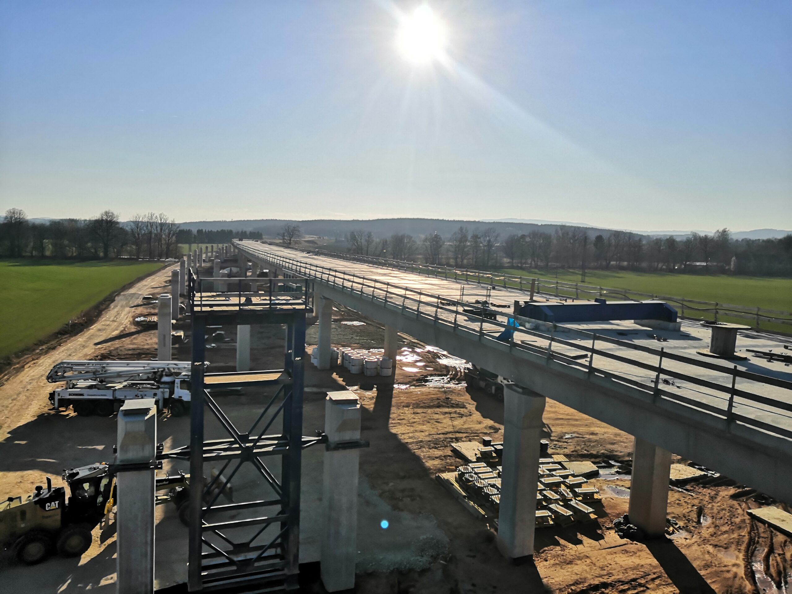
800 m bridge was designed as a flyover with 19 spans.
It contains 2 parallel decks with the width of 14,4m.
The height of the bridge above the ground is 10 m at its highest point.  

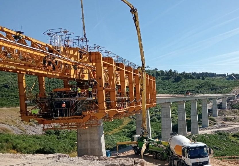
Strukturas Overhead MSS named SO 203 was used for construction of long deck of the bridge project D3 in the Czech Republic, close to Ceske Budejovice.

Highlights & Facts:
  • Max Span: 42,0m
  • Max MSS Span: 35m
  • Weight of Superstructure: Approx 28,6t/m
  • Width Of Bridge Slab: 14,4m
  • Min.Hor.Radius: R= 2700m
  • Max Crossfall: 2,5%
  • Max Long Slope: 0,7%
  • Deflection of MSS: MAX L/400

Client: Doprastav, a.s.

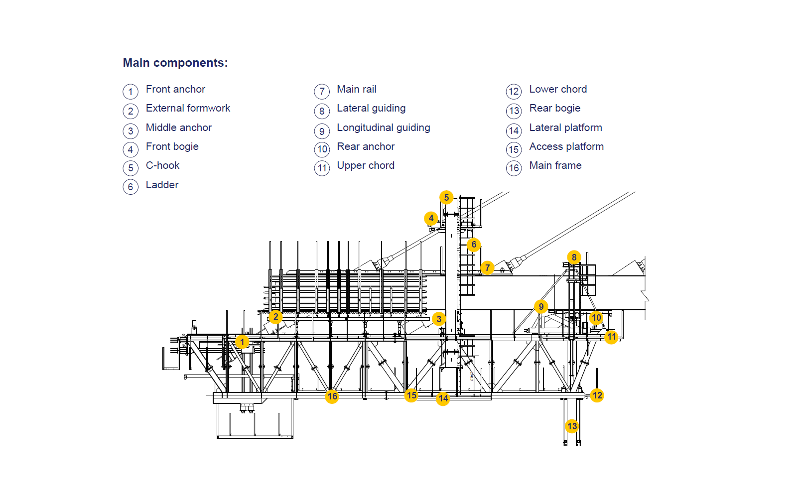
The Movable Scaffolding System was designed as an overhead type with two main I beams. Opening of the formwork and launching the MSS is was ensured by hydraulic cylinders.
The entire steel structure weighing 525 tons was manufactured in China, in a certified factory, and was transported to the construction site in 12 meter containers.
The complete production of the MSS took three months, and its subsequent transport across half the globe took about five weeks.
Assembly took place completely directly on the construction site using 30,000 high-strength bolts.
Typical span by span concreting cycle of 42 m length bridge spans takes 14 days.

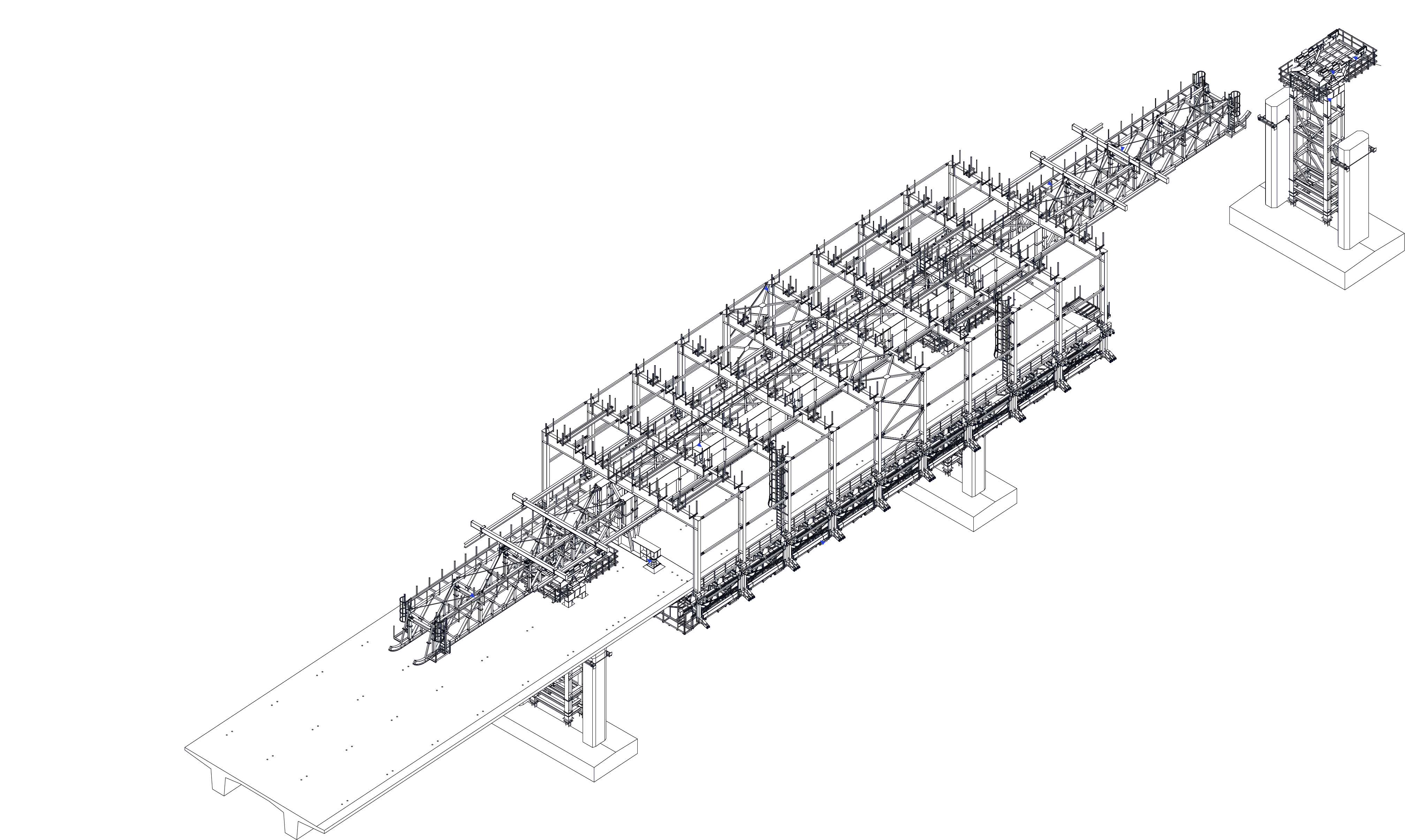
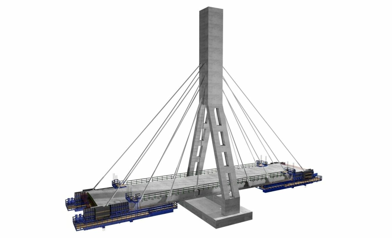
MSS SO 203 - 3D model picture
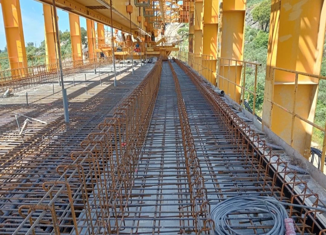
STRUKTURAS Overhead MSS SO 203 at concreting first span second deck of project D3 close to Ceske Budejovice in the Czech Republic.

The story of legendary MSS Drammensvogna

The story of legendary MSS Drammensvogna – 50 years in action 
 
Last week we signed one more MSS redesign contract with Skanska, who owns legendary MSS Drammensvogna.
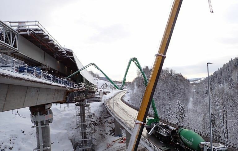
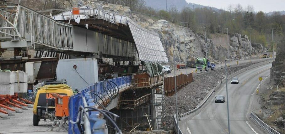
This time it shall be used at bridge Vadløkkjbrua on the E6 south of Trondheim, Norway.
 
Vadløkkjbrua will be the 19th project made with this MSS!
 
MSS Drammensvogna, one of the first MSS was builded in 1973 for Norway the motorway bridge in Drammen, Norway.
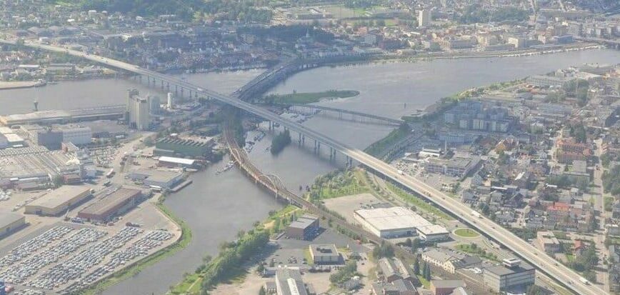
The E18 motorway bridge in Drammen is a four-lane girder bridge on the E-18 that crosses the outlet of the Drammen river between Brakerøya and Bangeløkka. The bridge has free spans of up to 60 meters and a sailing height of up to 12 metres.
Until now it is the longest bridge in Norway – 1,890 meters!
Movable Scaffolding System - MSS
Revolutionary MSS technology has proven its productivity.
The contractor for the bridge was Ingeniør Thor Furuholmen A/S, one of the largest companies in Norway at the time. They later merged with Ing. F. Selmer A/S to Selmer – Furuholmen AS, which today is Skanska Norge AS.
In collaboration with the consulting company Taugbøl & Øverland A/S (now COWI), the MSS was designed and put into production.
Construction work began in the autumn of 1973. The span by span casting of the bridge deck was carried out with a newly developed type of MSS, 131 meters long (800 tonnes weight), which enabled full casting at a speed of up to 100 meters of bridge per 14 days. Bridge deck has been casted 4 weeks before end of construction schedule.
 
Since that time the MSS Drammensvogna has been redesigned for many bridge projects in Nordic countries as underslung and overhead MSS.
On the engineering side, competence on the equipment has been maintained internally at Skanska, and there has also been good cooperation with for the consulting with us –  company Strukturas as.
 
All the projects accomplished with the Drammensvogna MSS:
1. E18 Drammen Drammensbrua 1973-75
2. E39 Kristiansand Gartnerløkka bridge 1978
3. Stockholm Johanneshov Bridge 1981-83
4. Strømstad Skee bridge 1986
5. E6 Oslo Lodalen bridges 1986-87
6. Sweden Obbola bridge 1988-89
7. Molde Bolsøy Bridge 1990
8. Skien Menstad bridge 1990-91
9. Askøy Askøy Bridge 1990
10. Storeklubben, Askøy Storeklubben viaduct 1989
11. Troms Dyrøy Bridge 1994
12. Porsgrunn Frednesbrua 1994-95
13. Gardermobanen Mork/Nessa/Kvisldalen 1995-96
14. Sykkylkven Sykkylvsbrua 1999-2000
15. E18 Drammen Parallel motorway bridge 2003-2004
16. E16 Bagn Bagn bridge 2017
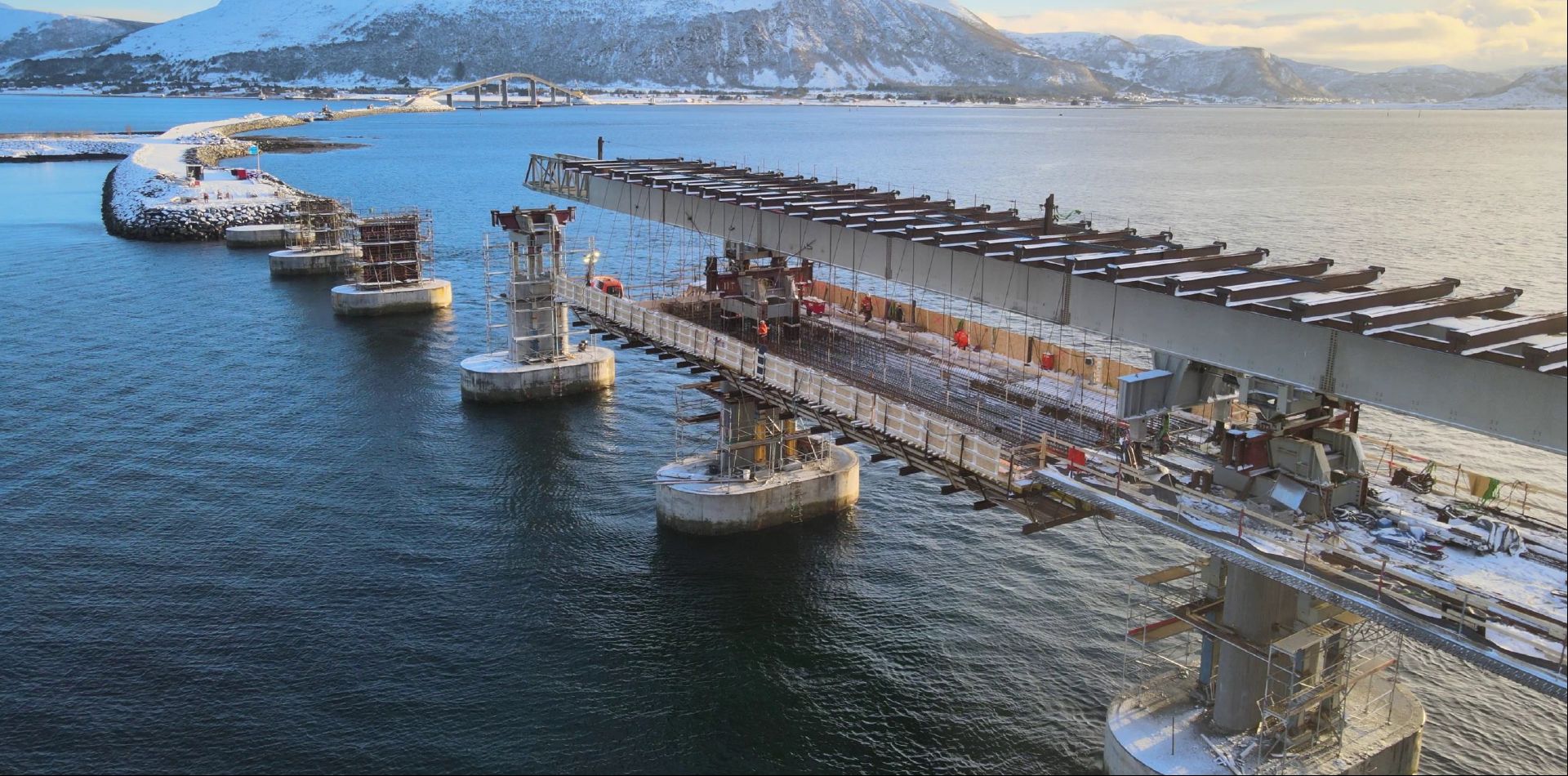
17. Nordøyvegen Lauke and Hamnaskjersund bridge 2020-21
18. E16 Bjørum-Skaret Isielva bridges 2022-24
19. Vadløkkjbrua on the E6 south of Trondheim 2024-25
 
Founder of Strukturas Tore Gjølme has followed this MSS since the beginning and will participate also at the 19th project for Drammensvogna. 
He is 78 years old and still going strong!
 
Credits to Statens vegvesen – Norwegian Public Roads Administration

Follow us on social media for more turnkey projects!

 Underslung Form Traveller Ariari Puerto Lleras, Meta, Colombia

Underslung Form Traveller Ariari

Underslung Form Traveller Ariari – Puerto Lleras, Meta, Colombia

Connecting the downtown area of Puerto Lleras with the existing Vista Hermosa county road, known as “Trocha Siete” with a bridge over the Ariari River.
It is a cable-stayed bridge with a length of 270 m, made up of spans of 70 m, 135 m and 70 m and a deck width of 11.6 m. Bridge supported by two pylons approximately 52 m high and 20 m wide at the base.
The superstructure is made up of a concrete slab that is supported on longitudinal and transverse by structural steel beams.
Balanced cantilever construction method of the deck – Cast-In-Situ with Form Travellers.

The Underslung Form Traveller solution can be adapted to different types of bridge decks, such as arch bridges and cable-stayed bridges, leaving enough room to assemble the temporary or final cable stays, and allowing easy launchback to the initial assembly position.
The external formwork of this type of Form Traveller is supported by the main structure, leaving enough room to install the pre-assembled rebar cage. When the rebar cage is pre-assembled, the Strukturas Underslung Form Traveller is the perfect choice.

Highlighs & Facts:

Segment Length: 7,75m
Length of Hammerhead: 19,9m
MAX Segment Weight: 132,7ton
MAX Width Superstructure: 12,8m
Min.Hor.Radius: R=1195m
Max Long Slope: 7,0%
Crossfall: 0%
Deflection of Main Beam: L/400
Critical Wind Speed During Launching: 20,0 m/sec
Critical Wind Speed During Concreting: 32,0 m/sec
Client: CONCREARMADO LTDA.
Project Location: Puerto Lleras, Meta, Colombia

STRUKTURAS
WE MAKE IT SIMPLE !

See the video below and do not hesitate if you wish to consult about your bridge!

TB Heubach Bridge demolition

MSS-Heubach-demolition-second-span-2
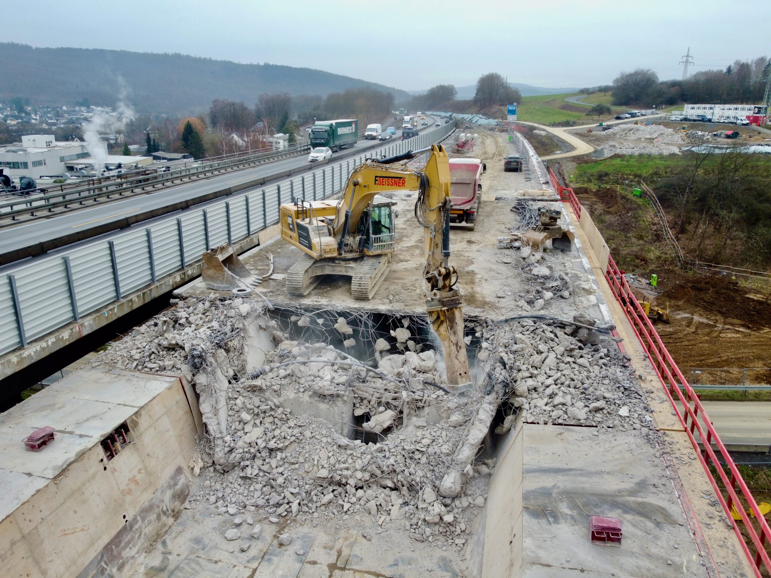
Implenia, a leading construction services company, decided to use an Strukturas Movable Scaffolding System (MSS) Underslung for the demolition of existing concrete decks on the TB Heubach Bridge in Germany.
 
Moreover this same MSS is also used for the construction of the bridge’s new TT section decks. 
 
The Heubach valley bridge consists of two parallel structures, which will be demolished and rebuilt in two construction phases.
Bridge info:
Year of construction of existing building: 1968
Length: 184 meters
Width: 16.5+16.5 meters
Bridge spans: 30,6 + 37,5 + 45 + 37,5 + 30,6 meters
Max. height above ground: 18 meters
 
Demolition of the old bridge and the construction of the new Heubach bridge was awarded by Die Autobahn GmbH des Bundes.

MSS at assembling final stage

Deck demolition

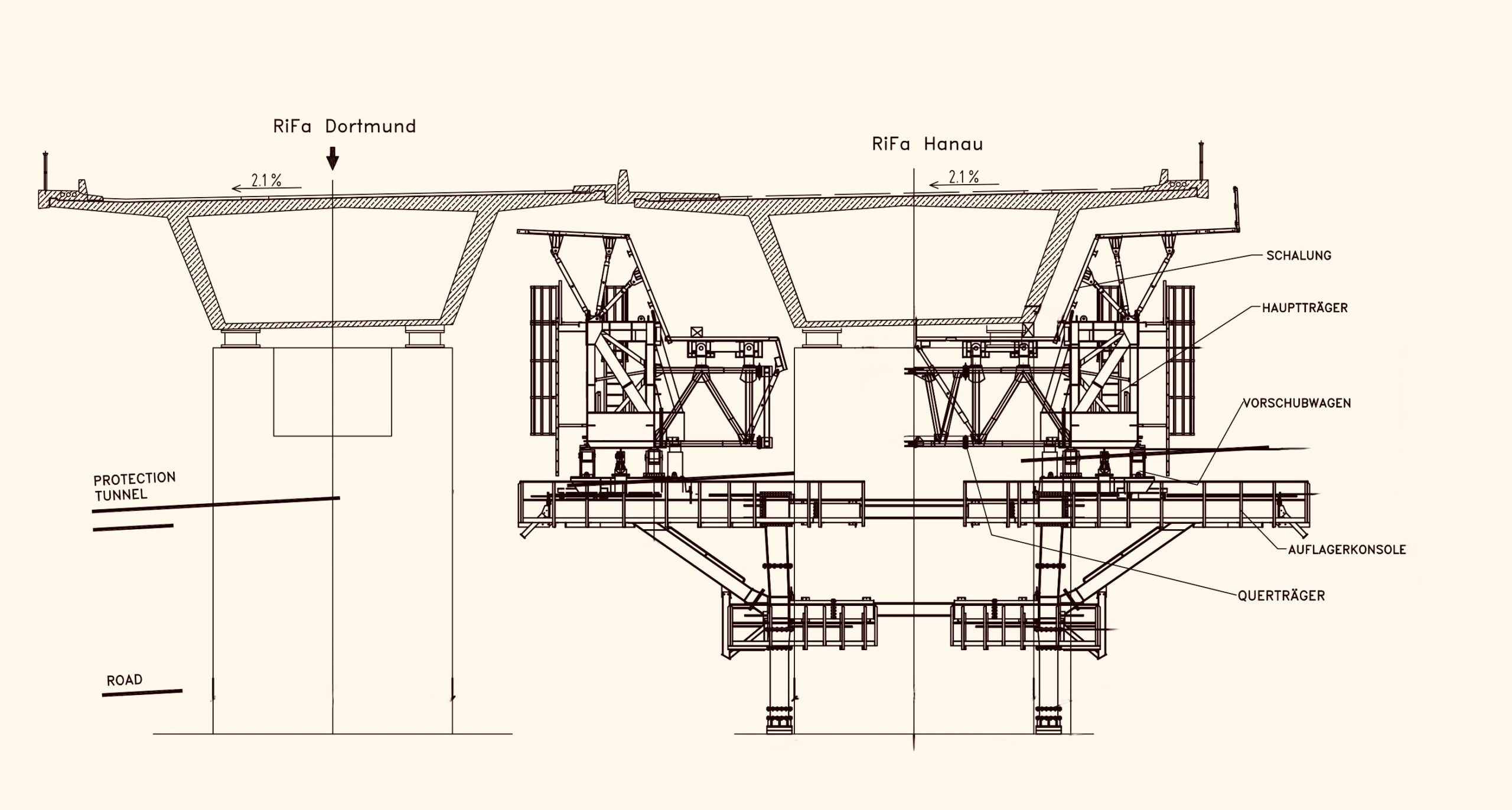
The Strukturas MSS solution is particularly innovative because it allows the conversion of the MSS formwork from a box section, which is used during the demolition phase, to a TT section, which is used during the construction of the new bridge decks. This approach saves time and resources, making the construction process more efficient.
The challenging conditions on the job site made the assembly of the MSS particularly demanding, and the Strukturas MSS assembly team had to plan and execute the operation to the best of their ability.
Movable Scaffolding System ensures the minimal intervention to existing infrastructure.
Using MSS for demolition allows the existing highway and the road bellow to remain open throughout most of the demolishing period.
The engineering challenge – to avoid an overload of the superstructure during the demolition and to ensure a safe load transfer within the load capacity of the MSS.
 

MSS general cross section view when used to demolish the existing concrete decks.

Highlights & Facts:
Max Span: 45,0m
Max MSS Span: 45,0m
Weight of the concrete bridge: Approx 250 KN/m
Width Of Bridge Slab: 16.5m
Min. Hor. Radius: R= 2500m
Max Crossfall: 2.1%
Max Long Slope: 0,63%
Deflection of MSS: MAX L/400

The demolition of old bridge structures with MSS is an effective and safe solution for many bridges.

See the video below and do not hesitate if you wish to consult about your bridge!

STRUKTURAS

WE MAKE IT SIMPLE!

Strukturas MSS approved as safe construction method to build bridge over the railway

The Bane NOR – Norwegian National Rail Administration has approved Strukturas MSS – Movable Scaffolding System as a safe construction method to build the bus road bridge over the railway line in Stavanger.

Movable Scaffolding System - MSS
MSS over the railway

The joint venture of Risa AS and Contur AS, with COWI as adviser, won the competition to build the Bussveien through Jåttåvågen, between Vaulen and Gausel in Stavanger.

The implementation of Strukturas as overhead MSS allows the railway to remain open throughout most of the construction period.
There is thus no need for a separate safety culvert over the railway, and train traffic can run while the biggest part of the concrete works is in progress.
When a contractor has to cast concrete or launch the overhead MSS over the railway they have to do it while there is no train traffic.

But they can do this work either at night when there is no train traffic or in periods where Bane NOR has approved stoppages in train traffic over several days. 
But most of the time concrete workers can work inside of the Strukturas as overhead MSS with ongoing traffic below.

If we had built in the usual way with traditional formwork, we would have had to secure the railway with a safety culvert and take additional safety measures to safeguard train traffic and other traffic under the bridge while the work is in progress, says Per Ove Stokkeland, project manager in Rogaland fylkeskommune .

Follow us on social media for more turnkey projects!

Strukturas – The Leading Bridge Building Equipment Supplier in Europe

Strukturas team congratulates founder Engineer Tore Gjølme on his 80th birthday

Movable Scaffolding Systems (MSS), Form Travellers, Launching Gantries, and full-service delivery for complex bridge decks.

Why Strukturas

For more than 30 years, Strukturas has helped contractors deliver over 300 bridges worldwide -safely, predictably, and on schedule. From concept engineering to dismantling, we supply bridge building equipment and the people, methods, and QA needed to execute critical-path concrete deck works for railway and highway viaducts, aqueducts, and long-span structures.

What sets us apart

  • Full portfolio: MSS (underslung & overhead), Form Travellers (FT), Segmental/Beam Launchers, Launching Gantries (LG).
  • End-to-end scope: design, engineering, fabrication, supply, rental, sale, sale-with-buyback, assembly, operation, dismantling planning, labour crew services.
  • Certified quality: Eurocode 3 / NS-EN 1993, EN-1090 (Execution Class II), steels Q235 / Q345.
  • Global footprint: European headquarters in Norway, with offices across Europe and Asia and agents in key markets.

What We Deliver: Systems That Fit Your Method

Movable Scaffolding Systems (MSS)

  • Configurations: Underslung and Overhead.
  • Use cases: In-situ bridge deck construction over water, traffic, and rail; constrained access; long approaches.
  • Engineering levers: span length, deck width, curvature radius, slope, load capacity, cycle time.
  • Features: Hydraulic systems, self-launching sequences, optimized transverse beams and supporting brackets.

Form Travellers (FT)

  • Variants: Overhead / underslung form travellers, segmental form travellers.
  • Method: Balanced cantilever for long spans, tall piers, and curved alignments.
  • Interfaces: Internal/external formwork, anchorage/brackets, predictable cycle control for cast in-situ boxes and U-shape aqueducts.

Launching Gantries & Beam Launchers

  • Segmental construction: Span-by-span or balanced methods for precast programs.
  • Beam launchers: Efficient placement for precast girder viaducts and approaches.

Where Our Equipment Excels

  • Viaduct concrete decks with repetitive spans.
  • Cast in-situ bridges where access is limited and logistics are constrained.
  • Full-span formwork scenarios that demand high productivity.
  • U-shape aqueducts and atypical cross-sections.
  • Over-water / over-rail alignments requiring self-launching and controlled possession windows.

End-to-End Services (Reducing Interfaces, Reducing Risk)

  1. Design & Engineering – method studies, preliminary sizing, detailed calculations, and constructability reviews.
  2. Fabrication & Supply – EN-1090 compliant manufacturing & QA, transport and pre-assembly planning.
  3. Commercial Modelsrental, sale, sale with buyback to match program horizons & redeployment plans.
  4. Assembly & Operation – site setup, commissioning, labour crews, supervision, cycle-time tuning.
  5. Dismantling Planning – safe-park strategies, retreat sequences, turnaround for next project.

Engineering & Technical Specifics

  • Geometry inputs: span length, deck width, curvature radius, slope.
  • Structural kit: internal/external formwork, supporting brackets, transverse beams tailored to box girder geometries.
  • Systems: synchronized hydraulic systems, controlled self-launching (underslung/overhead), defined load capacity envelopes.
  • Productivity: repeatable cycle time windows supported by crew models and shift patterns.

Standards, Certification & Materials

  • Eurocode 3 / NS-EN 1993 design basis.
  • EN-1090, Execution Class II fabrication control and traceability.
  • Steel grades: Q235 / Q345, selected for strength, weldability, and lifecycle performance.

Sustainability & Efficiency

  • Reuse, rental and sharing models to maximize equipment lifespan and minimize CO₂ footprint.
  • Efficient material usage via modular designs and redeployment planning.
  • Minimal environmental impact from self-launching methods that limit temporary works and ground disturbances.

Geographic Presence

A global supplier to contractors of railway and highway bridges, with project references across Europe, the Middle East, and worldwide.

Agents in: Azerbaijan, Bosnia and Herzegovina, Croatia, Czech Republic, France, Greece, Israel, Italy, Kazakhstan, Korea, Macedonia, Malaysia, Montenegro, Qatar, Romania, Singapore, Indonesia, Slovakia, Slovenia, Sweden, Taiwan, Turkmenistan, Turkey, Ukraine, United Kingdom.

Offices in: Norway (HQ), Austria, China, Estonia, Germany, Latvia, Lithuania, Poland, Portugal, Switzerland, Slovakia.

Track Record & Team

  • 30+ years of experience, 300+ bridges delivered.
  • International engineering bureau with several branches in Europe.
  • Proven references & case studies across geographies and delivery models.

Typical Engagement Flow

  1. Early inputs: alignment, span schedule, cross-sections, site constraints.
  2. Method screening: MSS vs. FT vs. LG vs. BL decision support with risk/constructability notes.
  3. Commercial fit: rental / sale / buyback with redeployment outlook.
  4. Execution plan: assembly, commissioning, cycle-time targets, QA plan, HSE envelope.
  5. Handover & dismantling: controlled retreat, asset preservation, documentation.

FAQ

Do you both rent and sell equipment?

Yes. We match rental, sale, or sale-with-buyback to program duration and your redeployment pipeline.

Can you operate the equipment with your crews?

Yes. We provide assembly, operation, and labour crew services, or we can supervise your crews.

What standards do you build to?

Design to Eurocode 3 / NS-EN 1993; fabrication to EN-1090 (Execution Class II) with documented QA; steel Q235/Q345.

Can you support over-water or over-rail projects?

Yes. We engineer self-launching MSS and method statements for constrained possessions and navigation windows.

Ready to build your next bridge more simple with worldwide bridge building equipment leaders? Talk to our engineers today and get your concept study started.

Follow us on social media for turnkey projects!

Choosing the Right Bridge Building Equipment Supplier for Your Project

Cross Tay Link Road bridge in Scotland Form Traveller

Choosing an equipment supplier is one of the most critical decisions in a bridge construction project, impacting everything from budget and safety to the final deadline. The right choice goes far beyond a simple price comparison. It involves a deep evaluation of a supplier’s capabilities and their ability to act as a true partner.

A top-tier supplier excels in three core areas: the quality of their equipment, the depth of their expertise, and the strength of their partnership. This guide breaks down what to look for in each of these essential pillars.

1. The Foundation: Equipment Fleet and Quality

The first step is to verify that the supplier has the right tools for the job and that those tools are of the highest quality.

The Essential Inventory

A specialized bridge-building supplier must offer a comprehensive range of machinery. This isn’t just about having one or two items; it’s about providing an integrated solution. Key categories include:

  • Heavy Lifting and Launching: This includes a variety of cranes (tower, mobile, gantry), launching girders for span-by-span construction, and specialized segment lifters.
  • Formwork Systems: A top supplier will offer advanced formwork, such as self-launching systems, that are essential for efficient on-site concrete casting.
  • Concrete and Foundation Machinery: This covers everything from concrete pumps and batching plants to pile drivers and excavation equipment.

Beyond the Inventory: Signs of Quality

Having the equipment is not enough. The quality and reliability of the fleet are what prevent costly downtime. Look for:

  • Modern, well-maintained fleet with clear maintenance records.
  • Safety and environmental compliance (e.g., ISO certifications).
  • Robust quality assurance including thorough inspections and material testing before equipment arrives on site.

2. The Differentiator: On-Site Technical Expertise

This is where a good supplier transforms into a great one. The support provided by their team is just as important as the machinery itself. On-site technical support is mission-critical for preventing delays and ensuring safety.

Correct Assembly and Commissioning

Specialized bridge equipment is not “plug-and-play.” An on-site technician from the supplier is the only person qualified to guarantee the equipment is assembled and calibrated according to the manufacturer’s exact specifications – a non-negotiable step for operational safety.

Immediate Troubleshooting to Minimize Downtime

When a key piece of equipment fails, the entire project can stop. The daily cost of a stalled infrastructure project can be astronomical. An on-site technician can often diagnose and fix an issue in hours, preventing a minor fault from turning into a multi-day delay.

Proactive Process Optimization

The best on-site support is proactive, not just reactive. An experienced technician can observe the workflow and suggest optimizations, such as a more efficient sequence for moving a formwork system. This expert guidance helps your team achieve maximum performance and can shorten the project timeline.

3. The Ultimate Goal: A True Strategic Partnership

Finally, the right supplier operates not as a temporary vendor, but as a long-term strategic partner invested in your project’s success. This value is seen in how they handle challenges and collaborate with your team.

Shared Risk and Innovative Solutions

A partner works with you during the planning stages, a principle known as Early Supplier Involvement (ESI). They use their experience to refine your equipment list, sometimes suggesting a different system that could save months from the schedule or improve safety. They share the responsibility of ensuring the project runs smoothly.

Unwavering Support in a Crisis

Projects rarely go exactly as planned. When challenges arise, a partner adapts with you. Their on-site team becomes an extension of your own, working to solve problems collaboratively. This immediate, unwavering support during a critical moment is the ultimate sign of a true partnership.

Long-Term Value

By working with an expert supplier, your own team’s skills grow. You establish a foundation of trust that makes future projects faster to plan and execute. The supplier becomes a go-to resource, providing a competitive advantage for your next tender.

Conclusion

The price on a quote reflects the cost of renting a machine. The true value, however, is found in the supplier’s ability to deliver reliable equipment, integrated expertise, and a genuine partnership that drives your project to a safe, on-time, and on-budget completion.

With more than 30 years of experience and over 300 bridge projects completed worldwide, Strukturas is uniquely positioned to meet these standards and help you complete your project in the best way possible.

Visit here to learn more.

Follow us on social media for turnkey projects!

Special services for one of our first customers

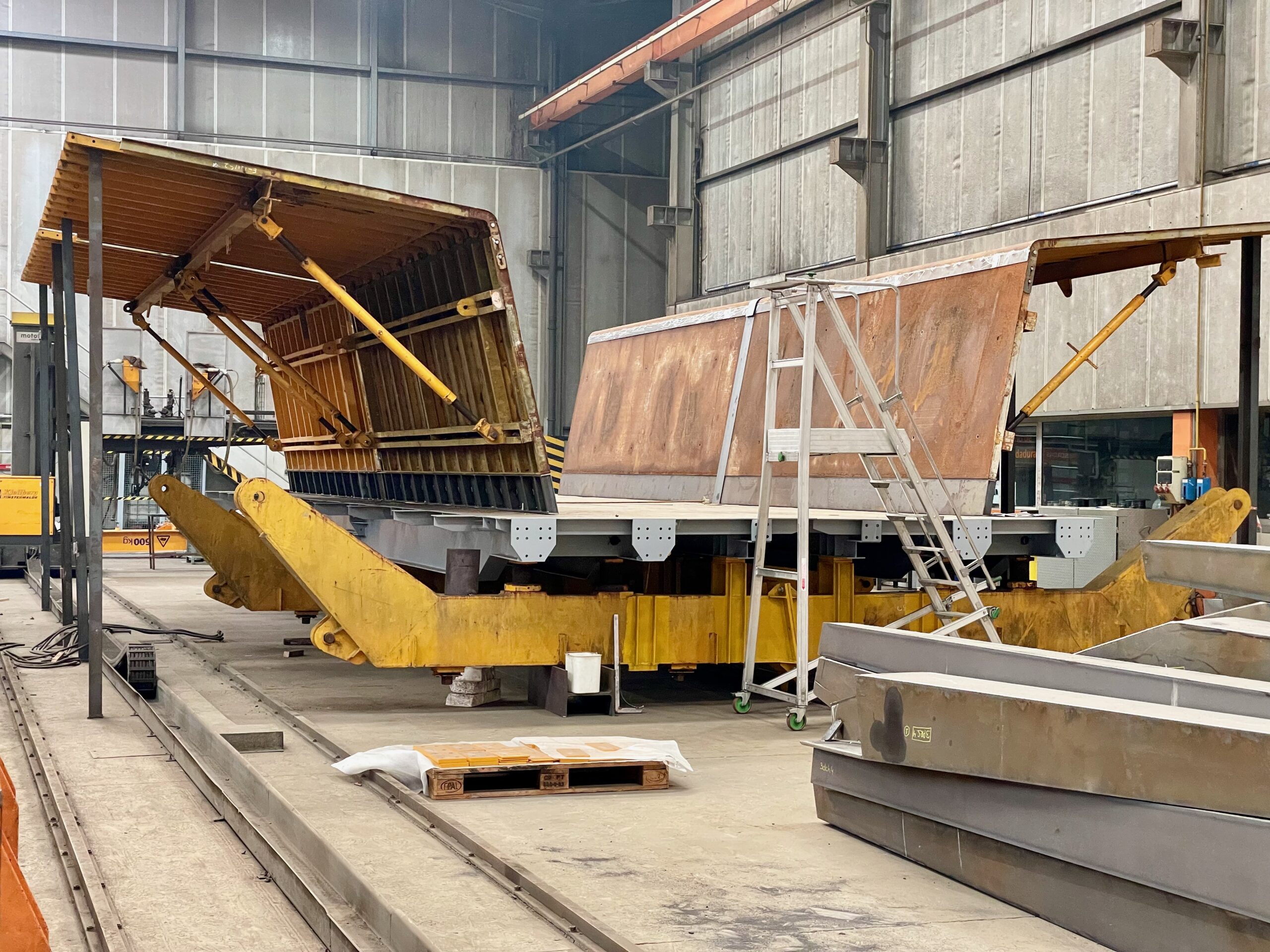
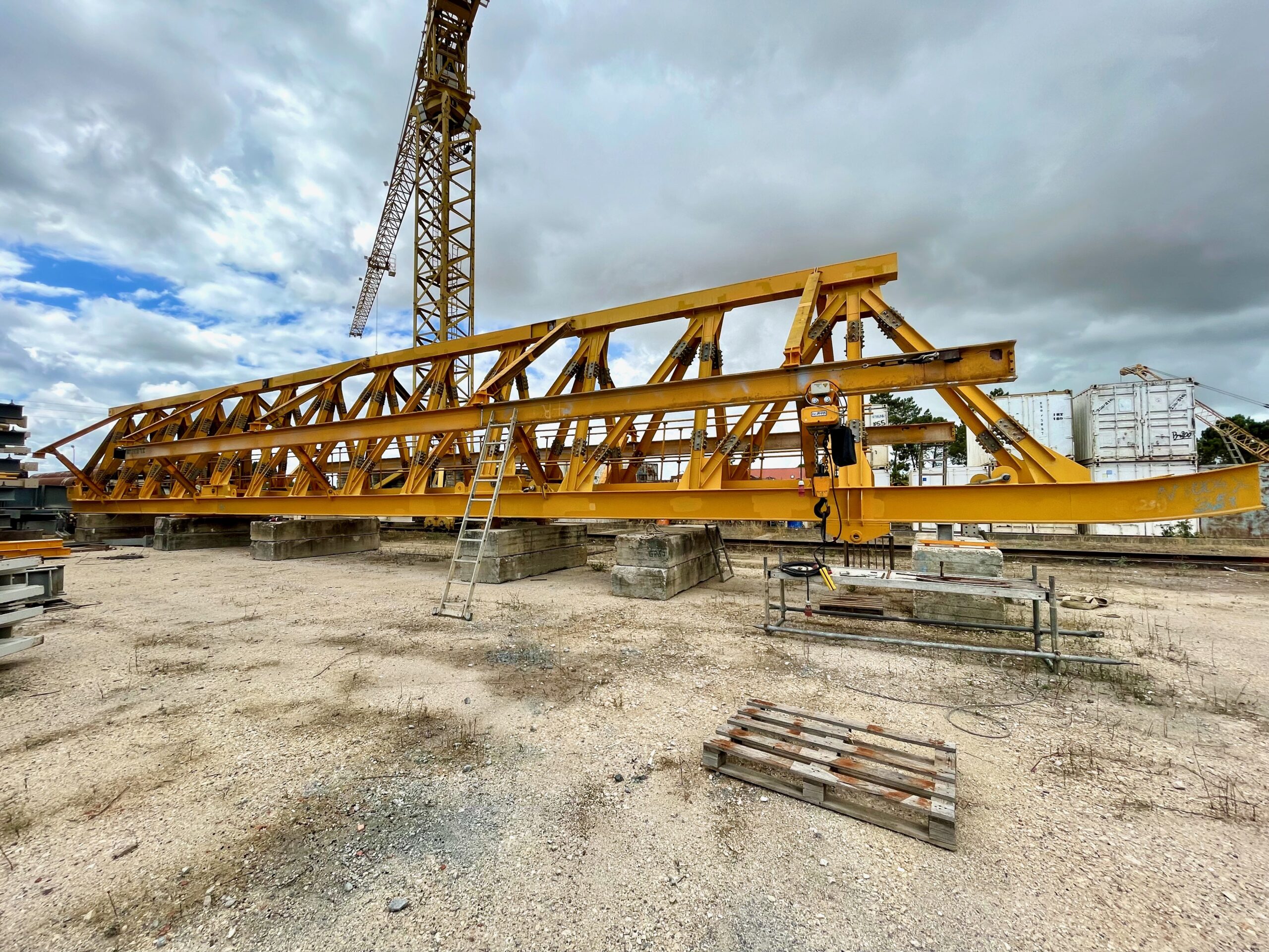
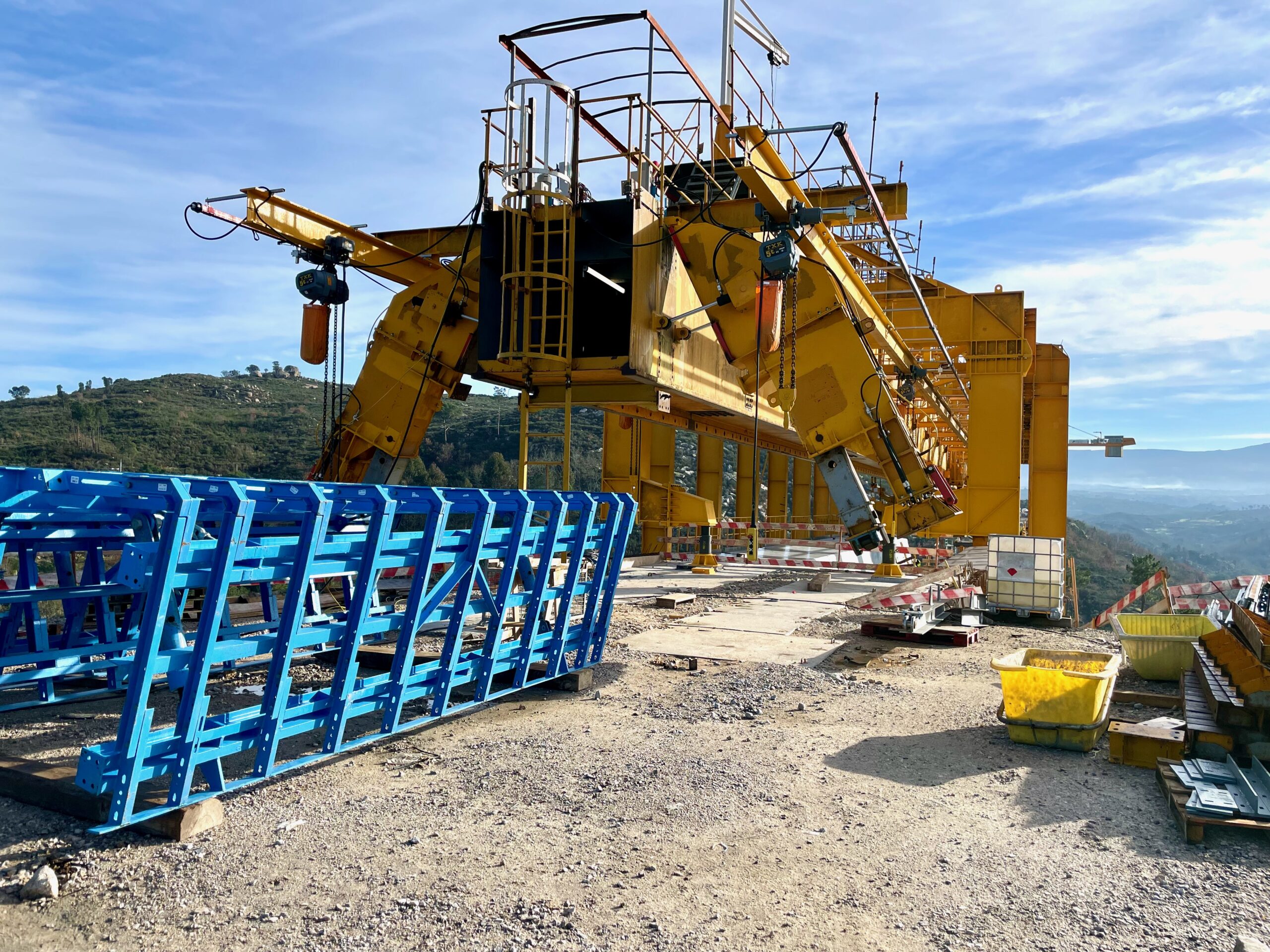
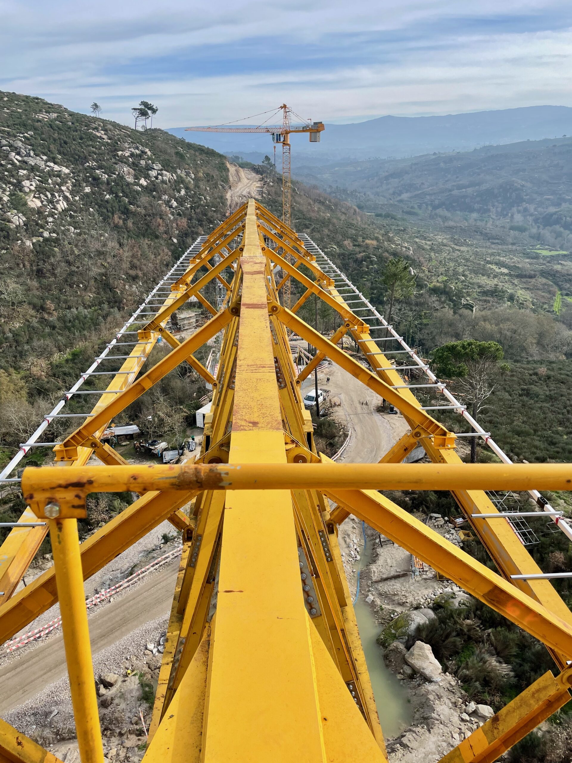
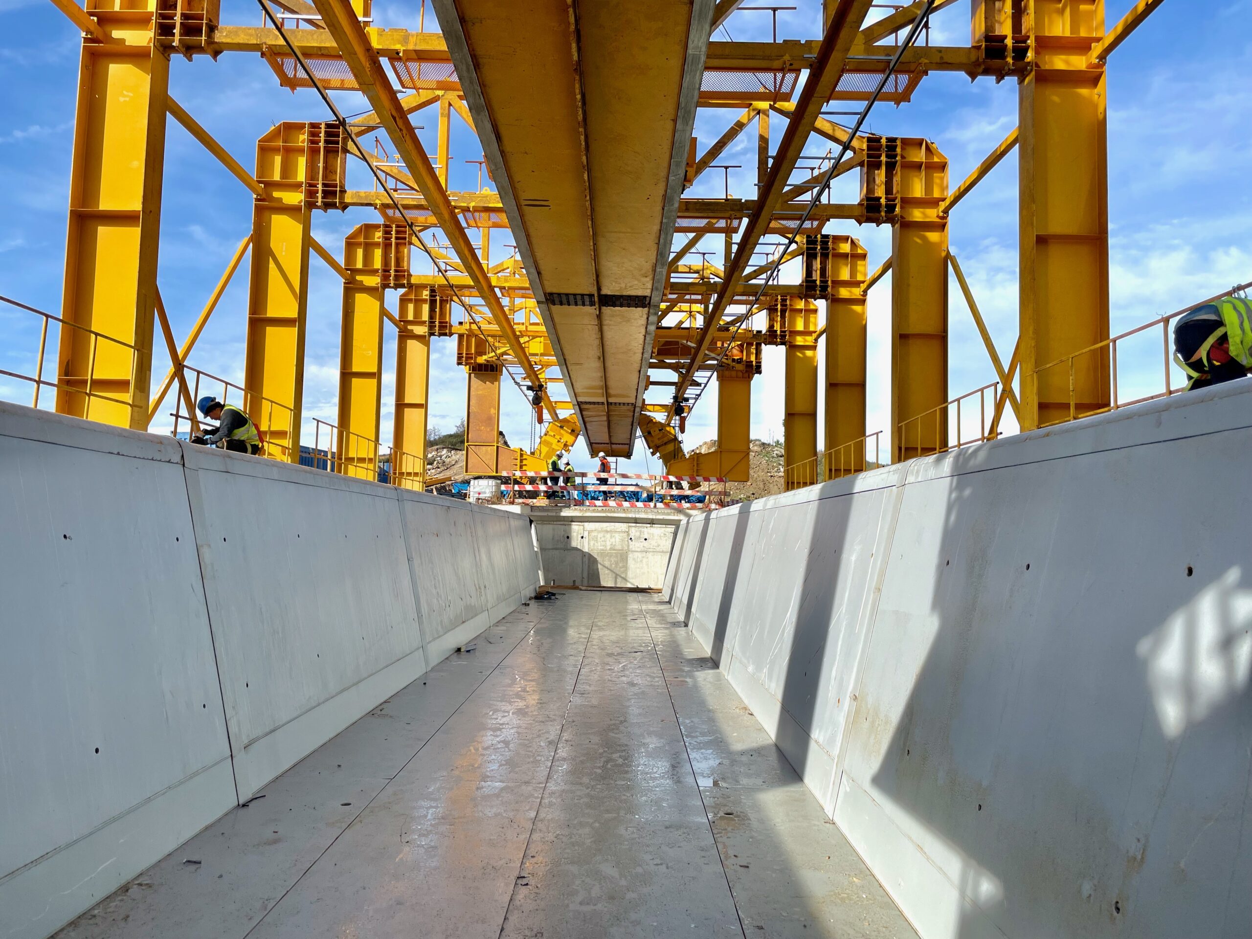
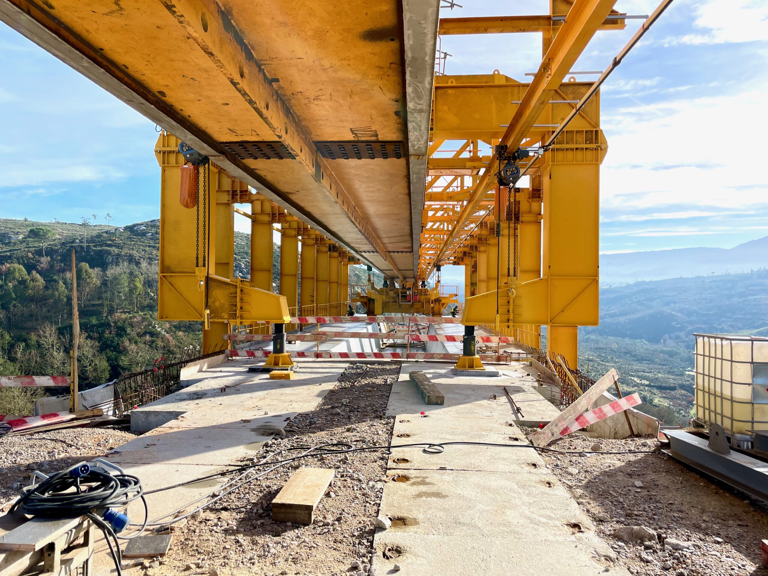
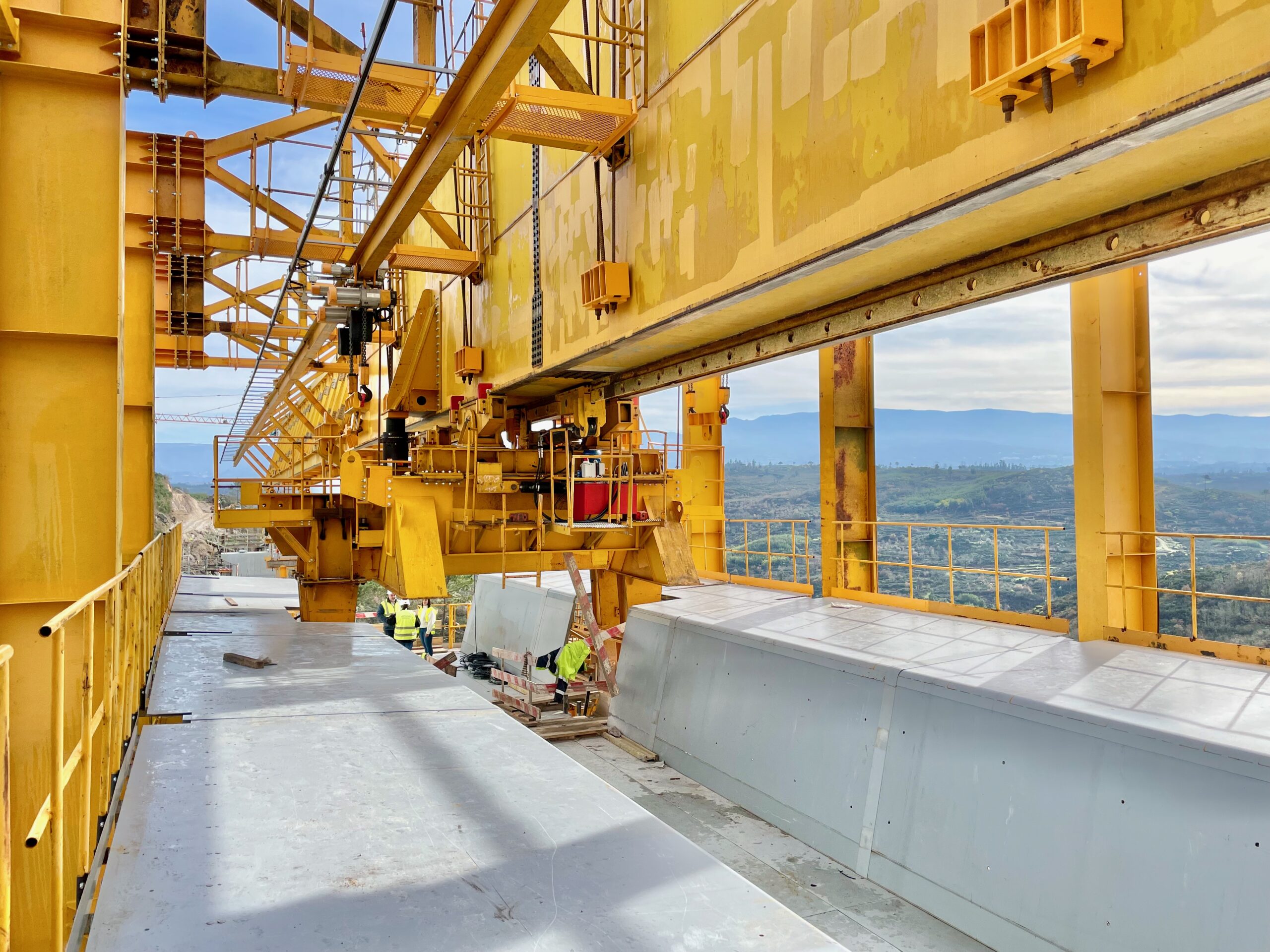
Our client, Mota-Engil, currently the largest Portuguese construction company present in various markets worldwide, has awarded Strukturas the redesign project of an Overhead MSS originally not provided by us and which had been stored for several years in their yard in Poland.

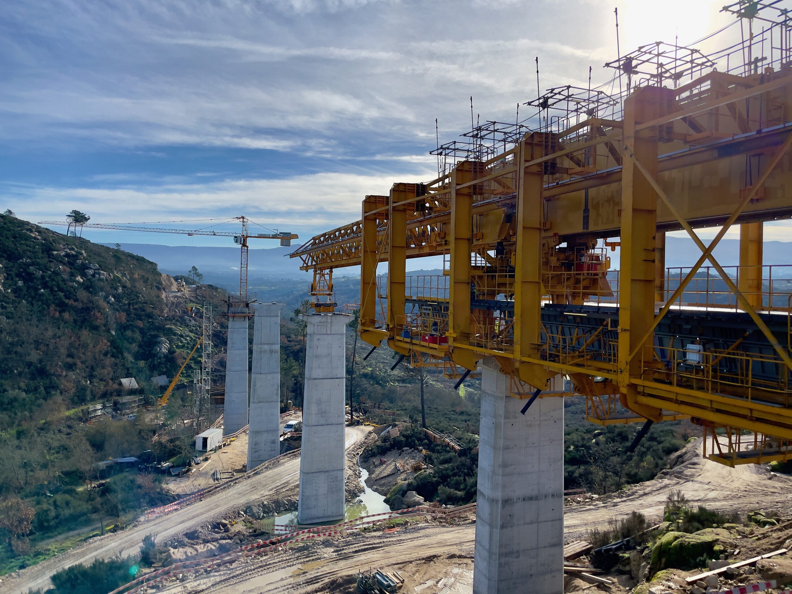
General Overhead MSS view
Rear launching support view
Workshop rebuilt stage
External steel formwork trial assembling at the steel workshop

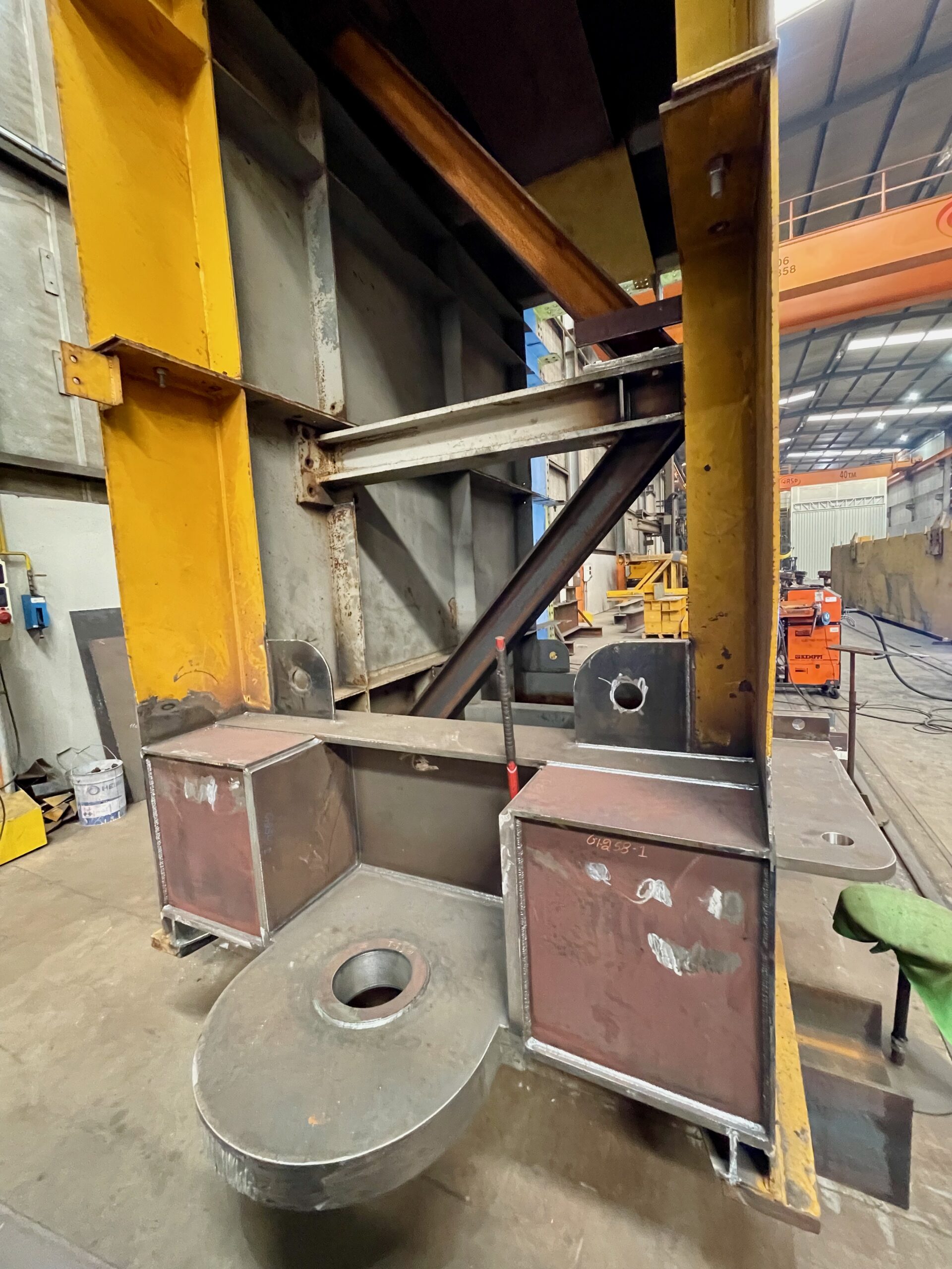
Strukturas’ redesign introduced significant modifications to the MSS, including a hinge joint between the main girder and the front nose, allowing it to be used on plan view curved decks, the addition of a rear concreting support, which allows for the transportation of pre-assembled U-shaped reinforcement using electrical winches, and the supply of a hydraulically operated internal formwork.

Front nose trial assembling at main yard
Hinge detail at main girder
View from the rear
Front nose general view

Mota-Engil transported the MSS from Poland to Portugal, where it is currently being used in the construction of railway viaducts. The rebuilt MSS steel structure was done in Portugal. Mota-Engil gave a special attention to pre-assembly and testing both at the workshop and at their central yard, due to the MSS being stored in Poland for several years.

Strukturas has been supplying various bridge building equipment, including Formtravellers FT and Movable Scaffolding Systems MSS, to Mota-Engil for around 30 years. Our the first supply was made in 1994 of an Underslung MSS to the company, that was then called Engil and later included in the Mota group, giving rise to the current Mota-Engil.

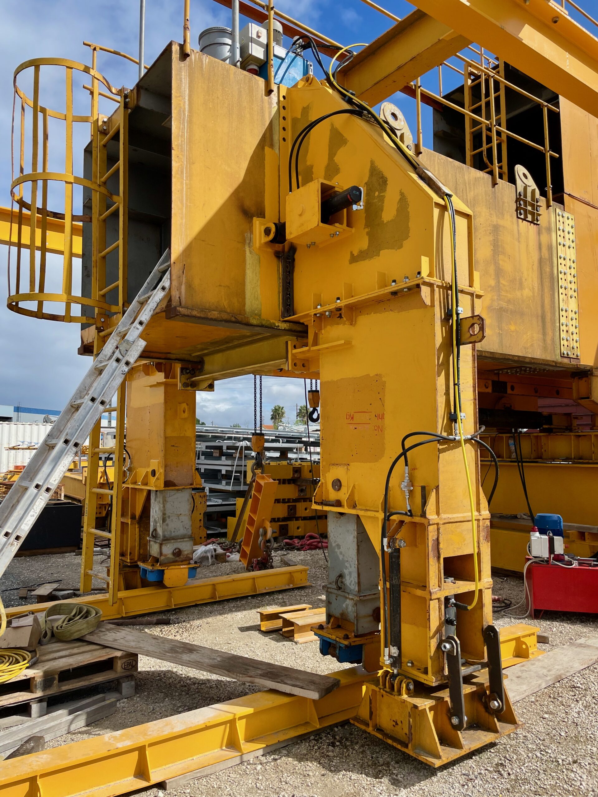
Hydraulic operated internal formwork delivered by Strukturas
External steel formwork
New rear concreting view
Front and intermediate supports

Formwork, Mechanisation and Site Operations in Movable Scaffolding Systems

Formwork, Mechanisation and Site Operations in Movable Scaffolding Systems

Beyond the main steel structure, the formwork system and site operations are critical to the performance and cost-effectiveness of a Movable Scaffolding System.


Internal and external formwork: configuration and mechanisation

In box-girder decks, both internal and external formwork can be integrated into Overhead or Underslung MSS. The internal formwork configuration is governed by the internal geometry of the box, not by the MSS type, so the solutions are broadly similar.

Typical characteristics:

  • Normal panel length (both internal and external): 5–6 m.
  • Internal formwork systems are most efficient when they are hydraulically operated:
    • The system often consists of formwork panels 5–6 m long,
    • A rail system, and
    • A transport trolley that moves the folded internal formwork from span to span, powered hydraulically.

To ensure efficient operations, external and internal formwork panels are usually connected by threaded ties (e.g. Dywidag bars) passing through the deck webs.


Geometric conditions for using mechanised internal formwork

To make full use of mechanised internal formwork, some design decisions must be taken early in the bridge conception:

  • The internal diaphragm typically located above the pier axis should be designed with a central opening of adequate size.
  • This opening must allow the passage of the folded internal formwork on its transport trolley.
  • Traditional diaphragms with narrow man-access openings are not compatible with fully mechanised formwork.

In theory, diaphragms can be concreted in two stages to create a larger passage opening, but:

  • This usually requires extensive use of reinforcement couplers.
  • The resulting cost is high and usually not competitive.

A better solution is to adjust the slab and web thicknesses near the diaphragm, allowing the diaphragm to be sized with a sufficiently large opening for the internal formwork.


Crossfall, rotation of the section and pour sequence

Deck geometry in cross-section is also important for MSS optimisation:

  • Ideally, the deck cross-section should be geometrically constant, and variations in transverse slope should be obtained by rotating the whole cross-section.
  • If the top slab rotates with the change in crossfall while the bottom slab remains horizontal, the web height becomes variable.
  • This often forces the deck to be concreted in two stages, complicating both the formwork and the construction cycle.

Designing with MSS in mind means favouring simple, repeatable cross-sections and rotations.


Formwork surfaces: plywood vs steel

The most common formwork surface in MSS is:

  • Phenolic plywood, typically 21 mm thick.

Steel formwork skins are technically possible but usually less attractive in practice:

  • Rebuilding or adapting steel formwork for future projects is expensive.
  • With plywood:
    • The underlying steel structure is easily reused and modified for new projects.
    • Plywood sheets are screwed to timber sections bolted to the steel ribs and can be replaced if the number of spans is large or the surface wears out.

For typical deck lengths and project sizes, phenolic plywood offers the best balance of cost, flexibility and finish quality.


Handling of reinforcement with Overhead MSS

Overhead Movable Scaffolding Systems are often equipped with electric winches that allow the transport of pre-assembled reinforcement cages or large reinforcement modules.

Some winch systems use toothed racks and toothed wheels, which:

  • Ensure safe handling of loads on decks with longitudinal slopes.
  • Reduce manual handling and increase productivity on site.

MSS as machinery under the Machinery Directive

Due to the presence of movement (launching, formwork opening/closing, internal trolley, etc.), Movable Scaffolding Systems and Formtravellers fall under the definition of machines in the Machinery Directive.

This classification implies:

  • Detailed risk analyses must be carried out.
  • The design must consider the risk hierarchy defined in the Directive.
  • All user safety aspects (access, fall protection, emergency stops, guards, etc.) must be addressed systematically.

The result is equipment that is not only structurally safe, but also safe to operate.


Construction cycle, crew and launching speed

The typical operations when using an MSS include:

  • Opening the formwork
  • Launching the MSS to the next span
  • Closing and adjusting the formwork (including cambering)
  • Preparing for reinforcement
  • Concreting and prestressing

The crew size required depends on span length, deck width and cycle time, but typically:

  • An MSS requires a team of around 12–14 people to handle operations efficiently.

Regarding launching:

  • A typical launching speed is about 10 m per hour.
  • Higher launching speeds are technically possible, but:
    • The kinetic energy of the moving MSS increases with speed.
    • Any accidental contact with supports or obstacles leads to much higher impact forces.
    • The small time savings from faster launching rarely justify the increased risk.

In practice, controlled, moderate speed is the standard for safe MSS operations.


Pre-assembly, transport and bolted connections

During original manufacture:

  • MSS steel structures are usually partially pre-assembled in the workshop.
  • All components are marked with references to simplify correct on-site assembly.

For transport:

  • Parts are typically designed to fit into 40’ containers or onto standard TIR truck platforms.

On site, proper planning of assembly and dismantling is essential:

  • Correct definition of lifting points and sequences.
  • Control of the centre of gravity in each assembly phase.
  • Safe access for cranes and auxiliary equipment.

Bolted connections in MSS can be:

  • Friction (slip-critical) connections with pre-stressed bolts, or
  • Shear connections with non-pre-stressed bolts.

Each option has implications:

  • Friction connections require:
    • Calibrated torque wrenches,
    • Strict tightening procedures,
    • Non-reuse of pre-stressed bolts.
  • Shear connections are usually simpler and cheaper, and are commonly adopted when design allows it.

Design Criteria Document: the key to choosing the right MSS

To evaluate whether a given MSS is suitable for a specific deck, a Design Criteria Document is essential. This document must clearly define:

  • Loads from the fresh concrete
  • Safety factors
  • Wind speeds:
    • During launching
    • During concreting
    • Under storm conditions
  • Materials and steel grades
  • Maximum span and deck weight
  • Live loads and construction loads, among other parameters

The cost and site performance of an MSS depend heavily on these technical definitions. A well-prepared Design Criteria Document is the foundation for choosing or designing the right system for each project.

STRUKTURAS
WE MAKE IT SIMPLE!

If you have any questions or would like to discuss the possibilities for your bridge project, please get in touch with your local agent or our head office in Norway: CONTACTS  

Movable Scaffolding Systems (MSS): Types, Design Rules and Advantages

Movable scaffolding system

Movable Scaffolding Systems (MSS): Types, Design Rules and Advantages

Movable Scaffolding Systems (MSS) have become one of the most efficient solutions for constructing prestressed concrete bridge and viaduct decks on piers, span by span. They combine structural efficiency with repeatable construction cycles and long equipment life.

Types of Movable Scaffolding Systems

There are two main types of MSS:

  1. Overhead Movable Scaffolding Systems
    • The main steel structure is located above the deck.
    • The formwork is suspended from this upper structure.

  2. Underslung Movable Scaffolding Systems
    • The main structure is located under the deck.
    • The formwork rests on the lower structure.

From the point of view of weight and cost, both types are generally equivalent when designed for the same maximum span and deck weight per meter.

Site assembly: practical differences between Overhead and Underslung MSS

The main difference between the two systems appears during on-site assembly and dismantling:

  • Overhead MSS
    • Can typically be assembled and dismantled behind the abutments.
    • This can simplify logistics, especially where access under the bridge is difficult (rivers, railways, deep valleys, congested traffic).

  • Underslung MSS
    • Is usually assembled between the abutment and the first (or last) pier.
    • Dismantling is typically done between the abutment and the first/last pier as well, unless a phased construction of the abutment allows part of the MSS to pass through it.

These aspects are crucial when planning crane operations, temporary works, and site sequencing.

Structural performance and deformability limits

In the structural design of MSS, deformations are carefully controlled:

  • For the overall MSS span, a maximum total deformation of L/400 is usually adopted, where L is the span of the MSS (axis-to-axis distance of its supports).
  • For local elements, such as individual formwork profiles, a typical limit is L/250 for the relevant element span.

This control ensures that the final deck geometry (including camber and alignment) stays within strict tolerances and that formwork reactions are close to those assumed in design.

Design codes and fabrication standards

The steel structure of a Movable Scaffolding System is usually designed and manufactured under well-defined standards:

  • Eurocode is used for the assessment of structural safety.
  • EN 1090 governs the quality control of steel fabrication.

In practice, MSS structures are also:

  • Modelled in 3D or represented in detailed 2D drawings.
  • Supplied with precise weights for all components, essential for planning lifting and assembly operations safely.

General advantages of MSS solutions

Key advantages of Movable Scaffolding Systems include:

  • Optimized material consumption in the bridge deck (concrete, reinforcement and prestressing) due to favorable construction load conditions.
  • Environmental benefits: MSS equipment typically has a useful life exceeding 50 years, making it reusable on many projects.
  • Low operating energy consumption compared to many alternative heavy construction methods.
  • Independence from ground bearing capacity and terrain relief, since the system is supported by the piers.

These features explain why MSS is often the preferred solution for repetitive spans on viaducts and long elevated structures.

Longitudinal slopes and safety in MSS launching

In theoretical terms, there is no strict limit on longitudinal slope for decks built with MSS. The longitudinal launching system is:

  • Hydraulically driven, and
  • Equipped with a mechanical brake, typically a pin system, that holds the MSS safely in place when the drive cylinder is retracted.

In addition, the hydraulic cylinders used for MSS launching are usually equipped with safety valves:

  • In case of a hydraulic pipe rupture, these valves block the oil inside the cylinder.
  • This stops unintentional movement and prevents uncontrolled displacement of the MSS.

These safety and control systems allow MSS to be used safely even on decks with significant longitudinal slopes.

STRUKTURAS
WE MAKE IT SIMPLE!

If you have any questions or would like to discuss the possibilities for your bridge project, please get in touch with your local agent or our head office in Norway: CONTACTS