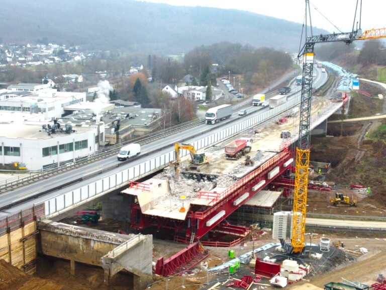
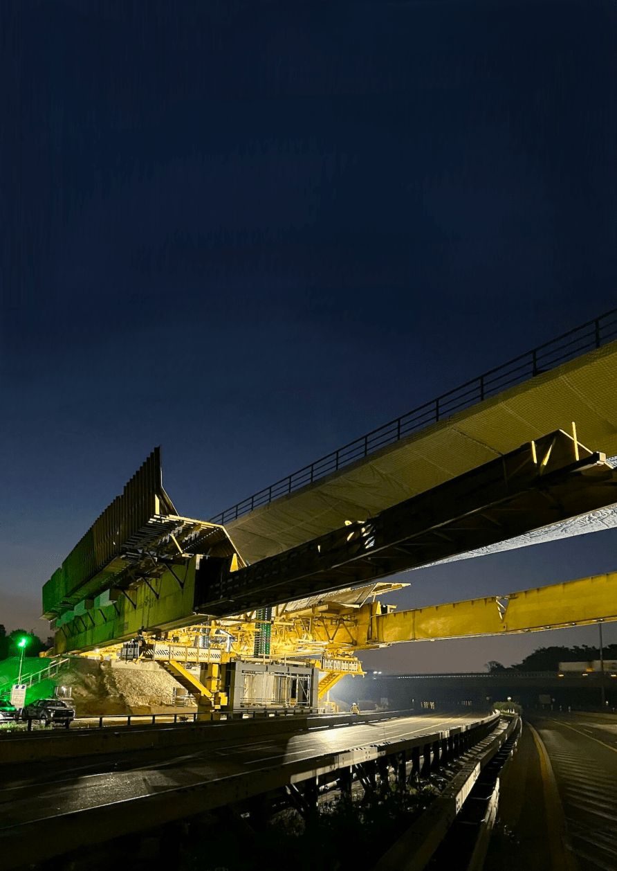
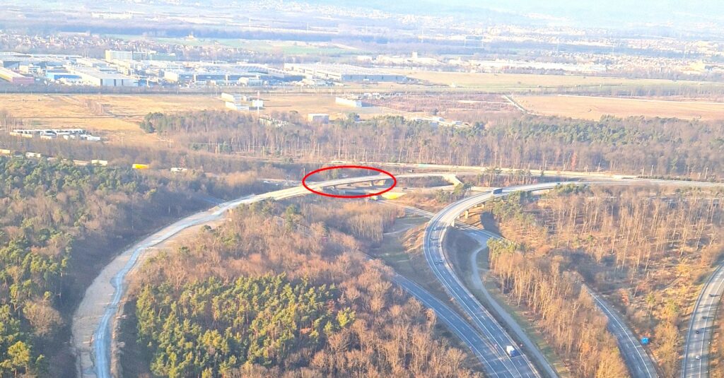
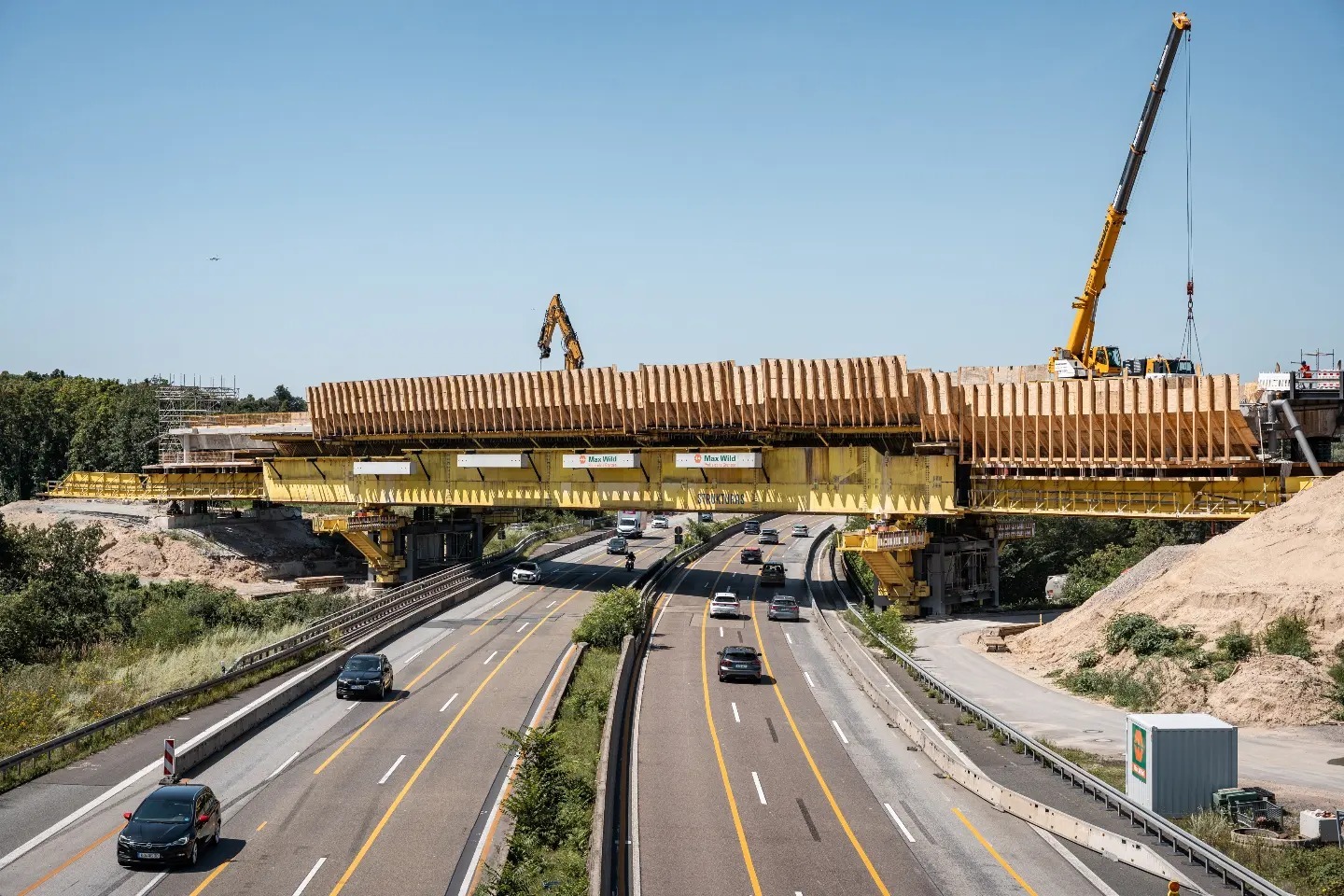
Randselva Bridge – Norway (built with no drawings)

Norway Randselva bridge MSS and FT

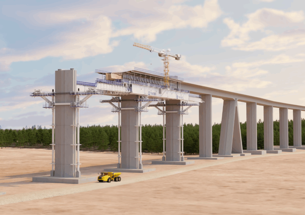
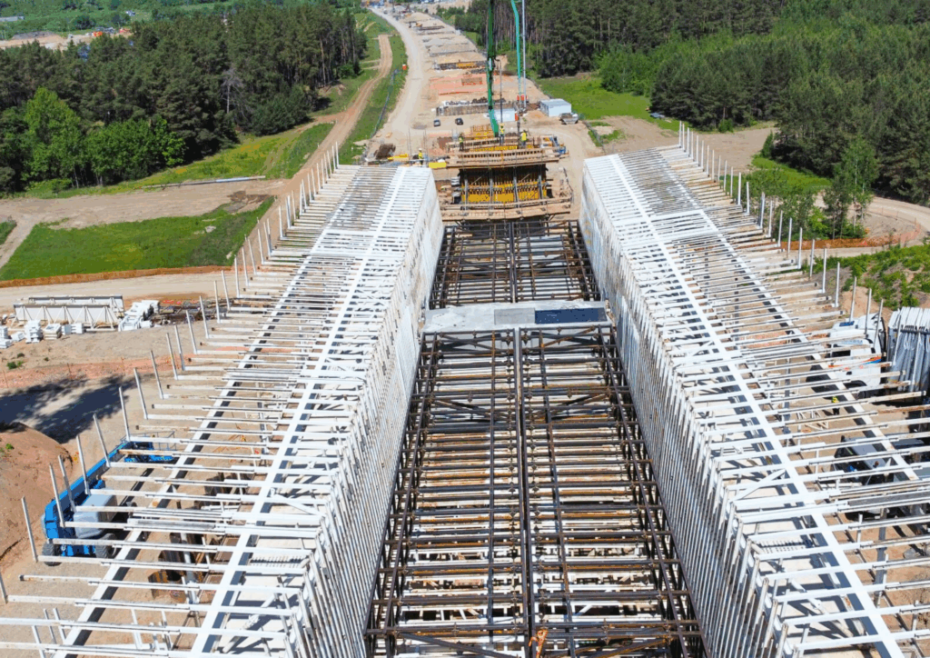
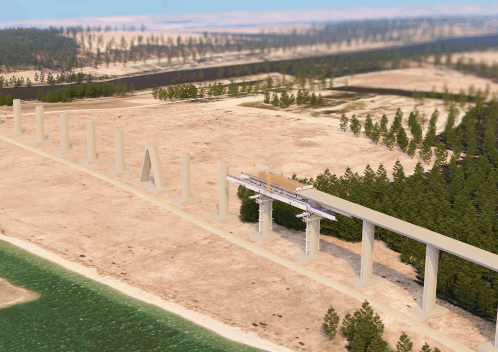
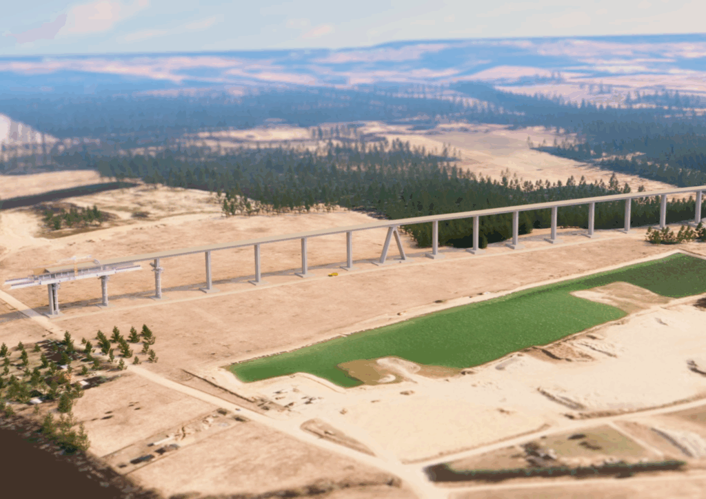
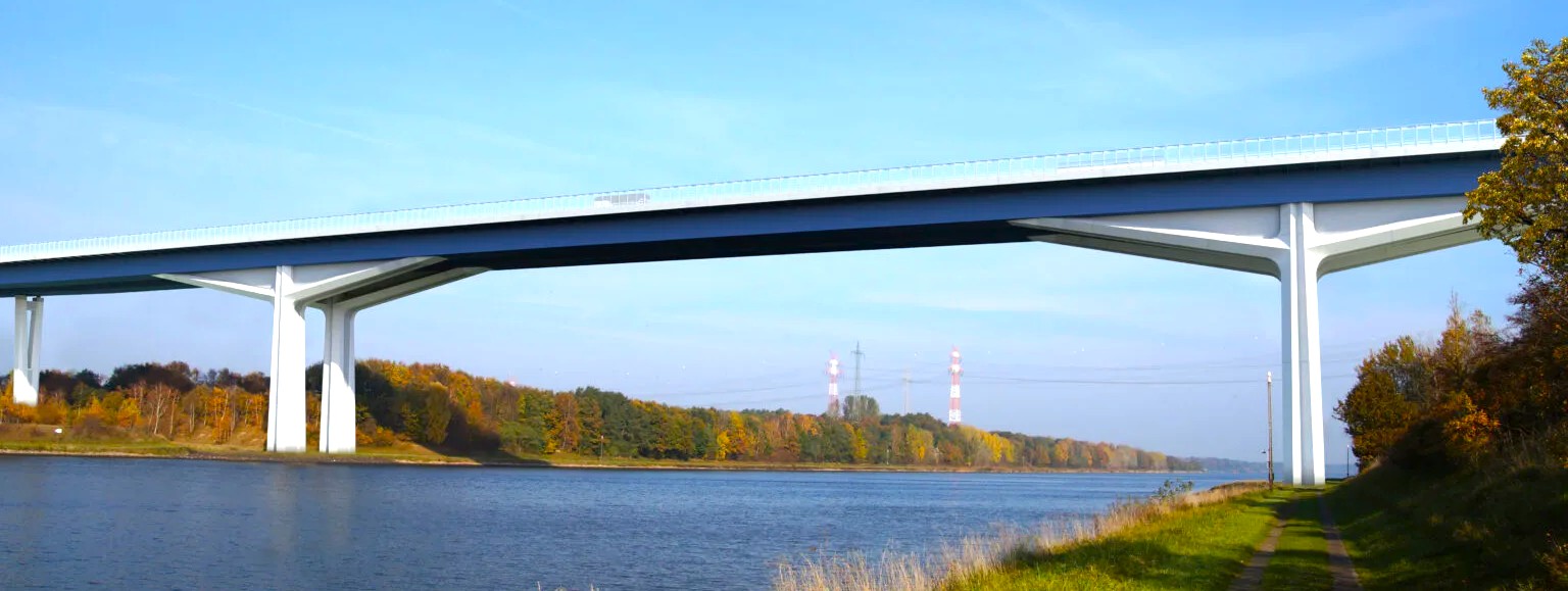
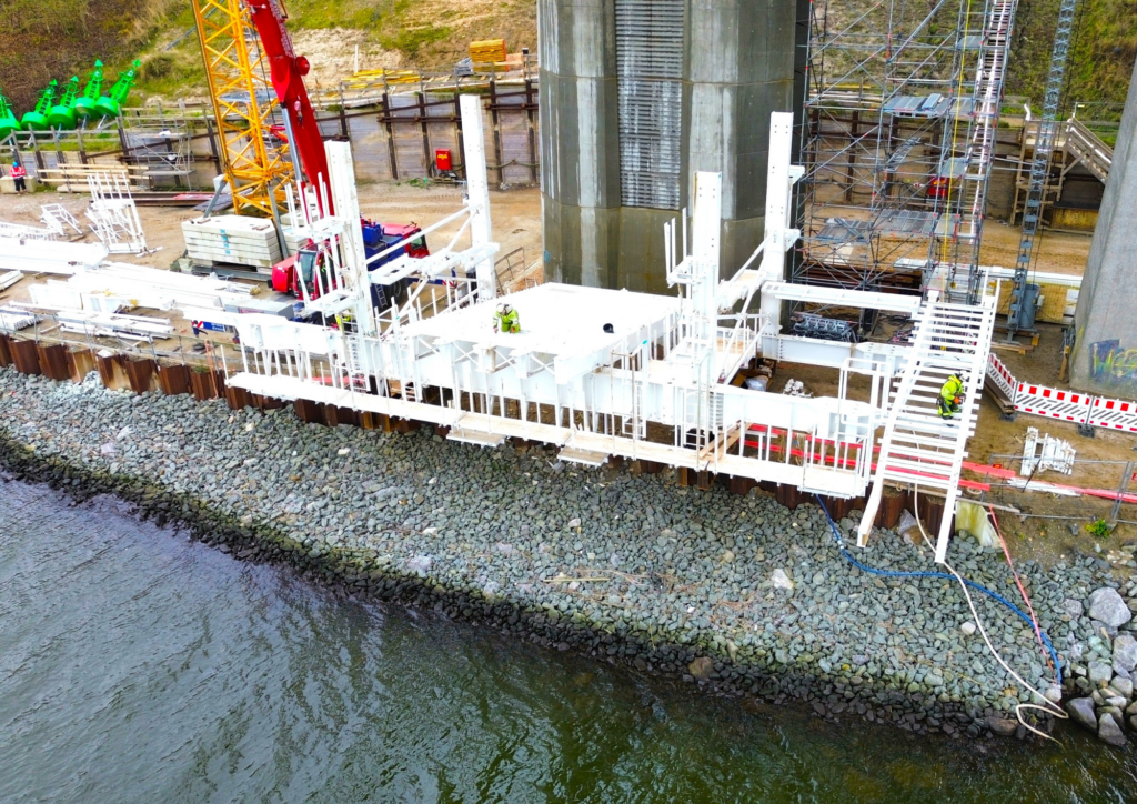
Randselva Bridge project in Norway – the 1st world’s longest bridge built with no drawings.

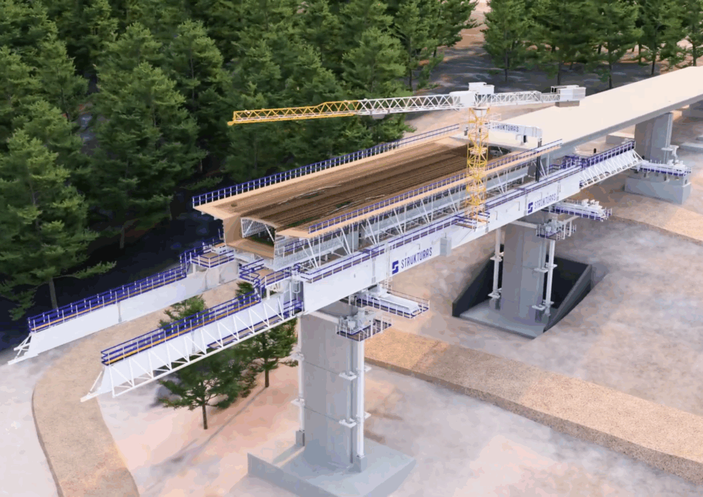
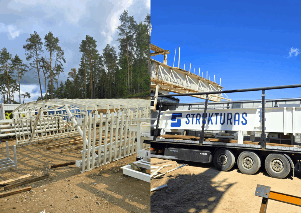
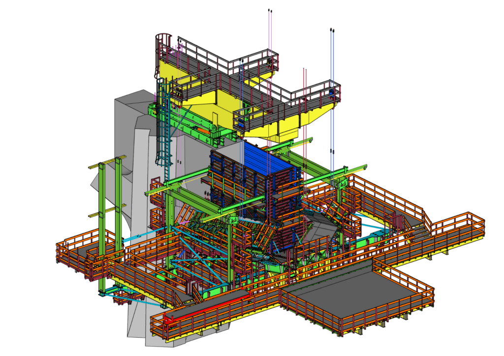
Strukturas is proud to have contributed with one Movable Scaffolding System and two Form Traveller pairs to the construction of the deck of this emblematic bridge.

Nestled in the stunning Norwegian landscape near Hønefoss, this remarkable bridge stands as a testament to a groundbreaking approach that redefines the future of engineering.

Few years have passed since the construction of this architectural marvel began, and throughout this remarkable journey remarkably, NOT A SINGLE PAPER DRAWING WAS USED. In an era where paper drawings have long been the cornerstone of construction, the Randselva Bridge project in Norway represents a journey into uncharted territory.

Contractor – PNC PORR Group

Advanced bridge building equipment, including 2 pairs of Form Travelers (FT) and Movable Scaffolding System (MSS), minimized labor and maximized machinery use.


Randselva bridge project in Norway isn’t just a means of crossing a river; it’s a symbol of innovation and a shining example of what’s achievable when visionary design meets cutting-edge technology. 

Here is the story of the Randselva Bridge, where the absence of paper drawings signifies a bold leap into the future of engineering.

KEY QUANTITIES:

CONCRETE: – 17040m3 (Abutments and Foundations 2 600 m3, Piers 2 540 m3, Decks 11 900 m3)

PRESTRESSING STEEL: – 620 ton

MILD STEEL: 2 445 ton

COST: 52 M €

Crafting a Vision. The journey of the Randselva Bridge began with a visionary concept design. Architects and designers embarked on a mission to create not just a functional bridge. However, a structure that seamlessly integrated with its stunning natural surroundings. Moreover the design principles prioritized both form and function as well as setting the stage for a bridge that would be as aesthetically pleasing as it was utilitarian.

The Randselva Bridge project in Norway isn’t merely a means of crossing a river; it’s an architectural masterpiece that enhances the landscape. The designers understood the importance of ensuring that the bridge harmonized with the natural beauty of the Norwegian terrain. This commitment to a holistic approach laid the foundation for a truly unique structure.

BIM & Paperless: The Digital Backbone

The project of Randselva bridge embraced a paperless revolution that changed the landscape of construction. In a departure from conventional practices, the entire project was driven by Building Information Modeling (BIM). Evidently this revolutionary approach allowed the project to progress for four years without a single traditional drawing.

BIM became the digital backbone of the Randselva Bridge, facilitating collaboration, communication, and decision-making. It streamlined information transfer, ensuring that everyone involved, from architects to contractors, had access to real-time data. The result was unparalleled efficiency and precision in construction.

The success of the Randselva Bridge project was a result of close cooperation among professionals from different countries. Leveraging the latest communication and data sharing technologies, they created a bridge that transcended boundaries.
Participants that use the BIM model

Oslo, Norway – BIM model coordination and quality control,

Copenhagen, Denmark – Parametric design, reinforcement,

Tampere, Finland – Parametric design, form and post-tensioning,

Katowice, Poland – Tekla reinforcement.

Bridging the Gap. One of the key factors that contributed to the success of the Randselva Bridge project, was the early involvement of contractors, as well as bridge building equipment suppliers.

Construction Method based on rule: Minimum Labor, Maximum Machinery

The Norway’s Randselva Bridge project proved a paradigm shift in the construction industry by embracing the philosophy of “minimum labor, maximum machinery.” Traditionally, bridge construction heavily relied on manual labor. However, this project recognized the advantages of mechanized construction methods.

Mechanized construction not only saved labor but also mitigated risks, shortened project duration, and improved safety and quality. It revolutionized the way bridges were built, leading to greater efficiency and precision.

STRUKTURAS tailored input with MSS and FT Construction Methods

Challenges and solutions:

  • Long spans for MSS with 3 spans of 60m and first span with 48 m. lead to very optimized MSS design.
  • Not much space for assembly at the first span. STRUKTURAS underslung MSS solution with assembly behind the abutment was used. MSS was launched into the first span.
  • The railroad (with traffic) goes diagonally under the bridge at the second span, which makes it impossible to use a traditional scaffolding.
  • The slope is big at the third and fourth spans with difficult support conditions for traditional scaffolding, nevertheless It was not the restriction for MSS.
  • Pier at axis 4 is 40m high. STRUKTURAS MSS Supporting Bracket system with block outs in the piers for load transfer to piers was used.
  • Small horizontal radius -1050 m. STRUKTURAS MSS includes the formwork which is made to adapt a small horizontal radius. However the launching of the MSS at small horizontal radius is possible due to rotation of the noses.
  • Difficult dismantling after finishing the fourth and last concreting between axis 4/5. The costs for dismantling was kept low by lifting up the MSS on the finished deck and transport back to the abutment for transport.

Outcome:

Revolutionizing Construction: STRUKTURAS spearheaded the transformation of construction methods by introducing advanced MSS and FT technologies. It allowed for a dramatic reduction in labor while maximizing the utilization of machinery.

Maximizing Efficiency: STRUKTURAS delivered 2 pairs of FT and 1 Underslung MSS for 60m spans inclusive assembly, operation and dismantling of the MSS.

Precise Execution: STRUKTURAS involvement ensured precise execution at every stage of construction.

Safety and Quality: STRUKTURAS prioritized safety and quality throughout the planning phase. Their input led to the development of construction methods that not only accelerated the project but also enhanced safety standards and overall quality.

Aquilino Raimundo, construction methods expert at Strukturas as, comments as follows: “The collaborative partnership between the designers, contractor and STRUKTURAS, with a significant focus on advancing MSS and FT construction methods showcased how early contractor involvement can lead to visionary designs that are not only aesthetically pleasing but, as a matter of fact, also constructible, efficient, and  innovative in construction.”

STRUKTURAS Integrated Services On-Site

From Supervision to Cambering. STRUKTURAS involvement extended beyond equipment supply. They offered integrated services on-site, ensuring that every aspect of construction was executed with precision. From supervision and mobilization to assembly, launching, and cambering, STRUKTURAS played a vital role in every stage of construction.

Øyvind Karlsen , comments: “The sum of the complex factors from the geometry of the Randselva bridge made the MSS technology from STRUKTURAS perfect. Our integrated services were crucial in ensuring that the project proceeded smoothly”.

Conclusion

The Randselva Bridge stands as a remarkable testament to what can be achieved with visionary design, cutting-edge technology, and global collaboration converge. With a focus on innovative construction methods, the bridge industry is transitioning towards mechanized construction, enhancing efficiency, safety, and quality.

As we look to the future, the lessons from the Randselva Bridge project inspire us to push the boundaries of engineering and redefine what’s possible in bridge construction. It’s a reminder that the future of engineering is not bound by paper but driven by innovation and collaboration.

Global collaboration and early contractor involvement played a key role in its success.

Randselva was the 20th bridge built in a cooperation between Strukturas as and ARMANDO RITO ENGENHARIA, SA . Our cooperation lasts more than 25 years:

1.       E16 Eggemoen – Åsbygda, Norway | Randselva brigde 2019
2.       IC5 – Murça (IP4) / Nó de Pombal, Portugal | Tua bridge 2010
3.       A32/IC2 – Oliveira de Azeméis / IP1 (S. Lourenço), Portugal | Canedo viaduct 2010
4.       A32/IC2 – Oliveira de Azeméis / IP1 (S. Lourenço), Portugal | Ínsua I bridge 2010
5.       Estrada Catete/Muxima – Província do Bengo, Angola | Kwanza II bridge 2009
6.       Estrada Catete/Muxima – Província do Bengo, Angola | Kwanza bridge 2008
7.       A32/IC2 – Oliveira de Azeméis / IP1 (S. Lourenço), Portugal | Uima II bridge 2008
8.       A41 – Picoto (IC2) / Nó da Ermida (IC25), Portugal | Uima I bridge 2008
9.       A17 – Auto-Estrada Marinha Grande / Mira, Portugal | Mondego bridge 2008
10.  Express motorway Benguela / Lobito – Província de Benguela, Angola | Catumbela bridge 2007
11.  A17 – Auto-Estrada Marinha Grande / Mira, Portugal | Mondego bridge 2006
12.  IP3 – Scut Interior Norte, Portugal | Vila Pouca de Aguiar viaduct 2006
13.  Viaduct Rib Alcobertas, Portugal 2006
14.  A11/IP9 Braga-Guimarães – IP4/A4, Portugal | Vizela viaduct 2005
15.  A10 – Auto-Estrada Bucelas / Carregado, Portugal 2004
16.  A11/IP9 Braga-Guimarães – IP4/A4, Portugal | Vizela viaduct 2004
17.  A7 / IC5 Guimarães-Fafe, Portugal | Nepereira viaduct 2003
18.  A25 / IP5 Mangualde – Guarda, Portugal | V1 and V2 viaducts2003
19.  EN125 Portimão, Portugal | Arade bridge 2001
20.  A2 Southern motorway, Alcácer do Sal Portugal | Sado viaduct 1998

Youtube video

The bellow YouTube video explains in detail the Randselva Bridge design and construction as a Drawing Free Project.

Credits: Ministry of Bridges, Tiago Vieira @ ARMANDO RITO ENGENHARIA, SA, Oystein Ulvestad and Sweco

Follow the author at:
https://www.instagram.com/gabrielnevesmob/

https://www.linkedin.com/in/gabriel-neves-90813626/

New Overhead MSS project STAWOLA WOLA in Poland

STAWOLA WOLA Overhead MSS over river SAN DW855
New MSS project – STAWOLA WOLA – POLAND
 
We are thrilled to announce that we have started the Overhead Movable System mobilization in Stalowa Wola where STRABAG is building an extradosed bridge over river San. Construction of the bridge is part of STRABAG construction of DW855 on the Zaklików – Stalowa Wola section.

The extradosed bridge will be 1.76 km long and will be the longest bridge in the Podkarpacie region in the provincial road network. It will consist of four sections – independent piers.
 
Do you wonder what an extradosed bridge is? Check this: https://en.m.wikipedia.org/wiki/Extradosed_bridge
 
Highlights and facts:
  • Max. Span: 45,8m / 40m (Approach / River)
  • Max. MSS Span: 42m / 35.5m (Approach / River)
  • Weigth Of Superstructure: 257,2 Kn/M / 439.6 Kn/M (Approach / River)
  • Cantiliver: 9,160m / 6.0m (Approach / River)
  • With Bridge Slab: 16.48m / 19.38m (Approach Span)
  • Min. Hor Radius: 1200m (Approach Span Only)
  • Max. Crossfall: 2%
  • Max Long Slope: 2,5 % / 1,72 % (Approach / River)
  • Deflection Of MSS: L/400

Photo credits: Screen shots from YouTube video / Miasto Stalowa Wola

STRUKTURAS
WE MAKE IT SIMPLE!

STAWOLA WOLA Overhead MSS over river SAN DW855

To see more projects we have completed with movable scaffolding systems (MSS) SEE THIS LINK

If you have a project where you would like us to have a look and make a proposal, feel free to contact our local agent or our head office in Norway. CONTACTS  

Largest infrastructure construction site in Slovakia for Strukturas MSS

Strukturas overhead MSS in Slovakia R2 Kriváň - Mýtna SO 210

R2 Kriváň – Mýtna SO 210 Largest infrastructure construction site in Slovakia, year 2024

2 Strukturas MSS’es are racing in one project with 14 days typical cycle.

  • Blue Overhead MSS – Povazska
  • Grey Overhead MSS – Wisla

The highway project R2 Kriváň – Mýtna.

Contractors:

Contractual construction start: 03/2020

Contractual construction completion: 06/2025

Length of the construction site: 9104 m.

This section will include a 5-kilometer-long bridge overpass in the valley of the Krivánske potok.

This overpass is situated at a height of 15-45 meters above the route of the road I/16, in close proximity to high voltage and existing buildings and this is a largest infrastructure construction site in Slovakia.

STRUKTURAS
WE MAKE IT SIMPLE!

Strukturas overhead MSS in Slovakia R2 Kriváň - Mýtna SO 210

To see more projects we have completed with movable scaffolding systems (MSS) SEE THIS LINK

If you have a project where you would like us to have a look and make a proposal, feel free to contact our local agent or our head office in Norway. CONTACTS  

Cross Tay Link Road bridge built with Form Traveller

Cross Tay Link Road bridge in Scotland Form Traveller

Balanced Cantilever bridge of Cross Tay Link Road bridge in Scotland.

Destiny Bridge, the flagship structure within the Cross Tay Link Road project. Balanced cantilever bridge with 56 cast in situ deck segments.

In this project we use Non-symmetrical casting! 

The use of this method corresponds to the initial assembly of only one Form Traveller (FT) and casting of the corresponding segment.
This Form Traveller (FT) is then moved to the end of the cast segment, and the pair’s second Form Traveller (FT) is assembled.
The pair’s second segment is then cast.
Subsequent segments will be cast symmetrically.

Max. Segment Length: 5,6 m
Max. Segment Width: 15,44 m
Max. Segment Weight: 261 Tons with 4,6 m

STRUKTURAS
WE MAKE IT SIMPLE!

Client: Royal BAM Group

Photo credits to: Bridge construction consulting 

Cross Tay Link Road bridge in Scotland Form Traveller

To see more projects we have completed with form travellers SEE THIS LINK

If you have a project where you would like us to have a look and make a proposal, feel free to contact our local agent or our head office in Norway. CONTACTS  

Overhead Form Traveller for the Nydal bridge

Overhead Form Traveller Nydal bridge

The Nydal bridge – Nydalsbrua

Roundabout transition to the cable-stayed bridge.

Overhead Form Traveller with segment length of 8,50m.

The Nydalsbrua is a 183-meter long cable-stayed bridge over the Nidelva in Trondheim, which has replaced the existing Sluppen bridge.

Nydalsbrua is the winner of Norwegian Betongtavlen 2023!

Well done Nydalsbrua project team!

Skanska is the bridge’s contractor, Aas-Jakobsen AS designer and Plan arkitekter AS have designed Nydalsbrua.

The Statens vegvesen – Norwegian Public Roads Administration was the client.

Photo credits to Grzegorz Gucwa from Skanska team.

Overhead Form Traveller Nydal bridge

To see more projects we have completed with form travellers SEE THIS LINK

If you have a project where you would like us to have a look and make a proposal, feel free to contact our local agent or our head office in Norway. CONTACTS  

Span by span construction of the new TB Heubach bridge

Strukturas MSS Heubach new bridge construction
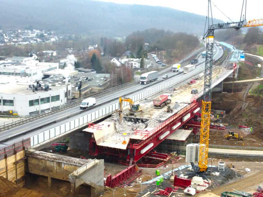
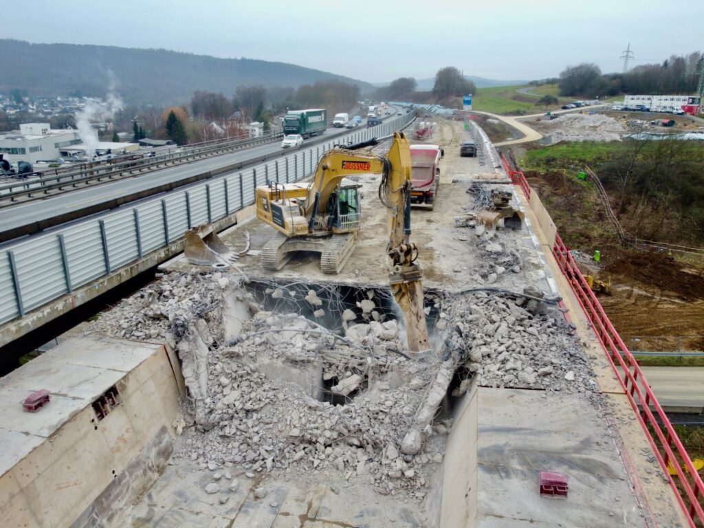
The Heubach valley bridge consists of two parallel structures, which were demolished and rebuilt in two construction phases.
 
Demolition of the old bridge and the construction of the new Heubach bridge was awarded by Die Autobahn GmbH des Bundes to the contractor Implenia.
Movable Scaffolding System ensures the minimal intervention to existing infrastructure.
Using MSS for new construction allows the existing highway and the road bellow to remain open throughout most of the construction period.
After finished demolition the same MSS is also used for the construction of the new TT section decks. As a result this approach saves time and resources, by making the construction process more efficient.

The MSS installation works was carried out by professional site team from Strukturas as.

Strukturas MSS Heubach new bridge construction

Highlights & Facts:

Max Span: 48,0m
Max MSS Span: 39,1m
Weight of the concrete bridge: Approx 426 KN/m
Width Of Bridge Slab: 18.3m
Min. Hor. Radius: R= 2500m
Max Crossfall: 4.53%
Max Long Slope: 0,63%
Deflection of MSS: MAX L/400

Strukturas MSS Heubach new bridge construction

The replacing of old bridge superstructures with MSS is an effective and safe technical solution.

Here is the link to the blog post about the demolition of the same bridge using the same MSS

See the video below and do not hesitate if you wish to consult about your bridge!

STRUKTURAS

WE MAKE IT SIMPLE!

First segments of balanced cantilever bridge are casted at Gostyn Bypass in Poland

Gostyn, Poland, Form Traveller

We are thrilled to share that first segments of balanced cantilever bridge are casted at Gostyn Bypass in Poland.

On behalf of Strukturas project team leaded by Maciej Masłowski we are sending our congats to Gostyn Bypass MGP/PZDd-14 bridge reinforced concrete team leaded by Alicja Kosz-Koszewska from G&M Sp. z o.o.
The consortium of MIRBUD SA and KOBYLARNIA S.A. is the General Contractor.

Strukturas has a great partner Hünnebeck by BrandSafway Poland team, leaded by Daniel Hutnik.

It’s good to feel a strong support and see great performance in designing and supplying formwork for bridge foundations, piers and hammerheads.

Information about the Form Traveller delivered to this project:
Max. Segment Length: 5,00 meters
Max. Segment Width: 11.78 meters
Max. Segment Weight: 175 tons with 5.0 meters
Max. Longitudinal Slope: 0,7%
Max. Crossfall: 2,0%

Facts:
✅Assembly of FT is done by Strukturas site team
✅ Hammerhead was asymmetrical with temporary supports on one side – asymmetric FT start
✅ Concreting segments and launching FT is symmetrical on each pendulum
✅ Strukturas is using Hunnebeck H20 wooden beams for external FT formwork.
✅ Besides FT steel structure Strukturas is supplying the client with all wooden parts too

STRUKTURAS
WE MAKE IT SIMPLE!

If you would like to learn more about using form travellers for your bridge, send us an email la@strukturas.no and we will contact you as soon as possible!

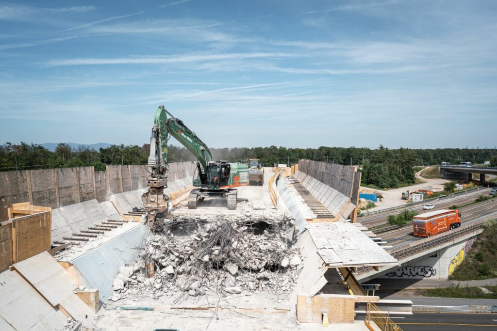
Span by span demolition of the bridges using the MSS

Krondorf Demolish first span

Span by span demolition of the bridges using  STRUKTURAS MSS – Movable Scaffolding System.

Contractors Eiffage , Implenia and Arlt Bauunternehmen GmbH are using this demolition method for their client Die Autobahn GmbH.

See the video about the project. For more videos about our projects, visit and subscribe to our Youtube channel  STRUKTURAS YOUTUBE CHANNEL

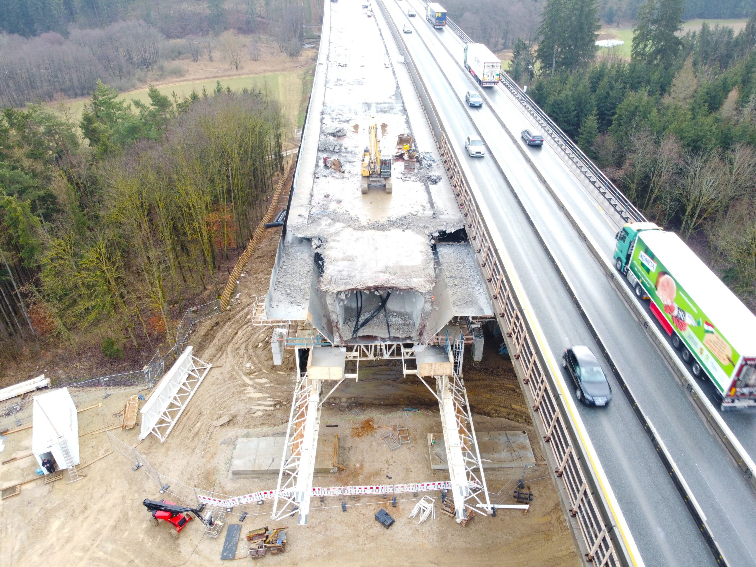
The demolition of the old bridge with MSS is an effective and safe solution:

– Minimal intervention to existing infrastructure.

– Using MSS for demolition allows the existing highway to remain open throughout all of the demolishing period.

– Moreover MSS allows the existing railway to remain open throughout most of the demolishing period.

– The MSS could be assembled on the ground and later could be lifted with 4 strand jacks.

– After finished demolition MSS could be lowered with 4 strand jacks on the ground for safe and productive MSS dismantling.

– The challenging MSS installation conditions can be carried out by professional site crew from Strukturas.

– The engineering challenge is to avoid an overload of the superstructure during the demolition and to ensure a safe load transfer within the load capacity of the MSS.

– After the demolition this same MSS could also be used for the construction of the bridge deck. This approach saves time and resources, making the construction process more efficient.

MSS-Heubach-demolition-second-span-2
Bridge demolition

If you would like to learn more about bridge demolition using Movable Scaffolding System, send us an email la@strukturas.no and we will contact you as soon as possible!

STRUKTURAS

WE MAKE IT SIMPLE!

#SpanBySpan #Bridge #Demolishing

#Brücke #Vorschubrüstung #Rückbau

#Bridge #ConstructionMethods

#Concrete #Project #Innovation

#Engineering #Technology

#Sustainability #Productivity

 
MSS-Heubach-demolition-second-span-2

The story of legendary MSS Drammensvogna

The story of legendary MSS Drammensvogna – 50 years in action 
 
Last week we signed one more MSS redesign contract with Skanska, who owns legendary MSS Drammensvogna.
This time it shall be used at bridge Vadløkkjbrua on the E6 south of Trondheim, Norway.
 
Vadløkkjbrua will be the 19th project made with this MSS!
 
MSS Drammensvogna, one of the first MSS was builded in 1973 for Norway the motorway bridge in Drammen, Norway.
The E18 motorway bridge in Drammen is a four-lane girder bridge on the E-18 that crosses the outlet of the Drammen river between Brakerøya and Bangeløkka. The bridge has free spans of up to 60 meters and a sailing height of up to 12 metres.
Until now it is the longest bridge in Norway – 1,890 meters!
Movable Scaffolding System - MSS
Revolutionary MSS technology has proven its productivity.
The contractor for the bridge was Ingeniør Thor Furuholmen A/S, one of the largest companies in Norway at the time. They later merged with Ing. F. Selmer A/S to Selmer – Furuholmen AS, which today is Skanska Norge AS.
In collaboration with the consulting company Taugbøl & Øverland A/S (now COWI), the MSS was designed and put into production.
Construction work began in the autumn of 1973. The span by span casting of the bridge deck was carried out with a newly developed type of MSS, 131 meters long (800 tonnes weight), which enabled full casting at a speed of up to 100 meters of bridge per 14 days. Bridge deck has been casted 4 weeks before end of construction schedule.
 
Since that time the MSS Drammensvogna has been redesigned for many bridge projects in Nordic countries as underslung and overhead MSS.
On the engineering side, competence on the equipment has been maintained internally at Skanska, and there has also been good cooperation with for the consulting with us –  company Strukturas as.
 
All the projects accomplished with the Drammensvogna MSS:
1. E18 Drammen Drammensbrua 1973-75
2. E39 Kristiansand Gartnerløkka bridge 1978
3. Stockholm Johanneshov Bridge 1981-83
4. Strømstad Skee bridge 1986
5. E6 Oslo Lodalen bridges 1986-87
6. Sweden Obbola bridge 1988-89
7. Molde Bolsøy Bridge 1990
8. Skien Menstad bridge 1990-91
9. Askøy Askøy Bridge 1990
10. Storeklubben, Askøy Storeklubben viaduct 1989
11. Troms Dyrøy Bridge 1994
12. Porsgrunn Frednesbrua 1994-95
13. Gardermobanen Mork/Nessa/Kvisldalen 1995-96
14. Sykkylkven Sykkylvsbrua 1999-2000
15. E18 Drammen Parallel motorway bridge 2003-2004
16. E16 Bagn Bagn bridge 2017
17. Nordøyvegen Lauke and Hamnaskjersund bridge 2020-21
18. E16 Bjørum-Skaret Isielva bridges 2022-24
19. Vadløkkjbrua on the E6 south of Trondheim 2024-25
 
Founder of Strukturas Tore Gjølme has followed this MSS since the beginning and will participate also at the 19th project for Drammensvogna. 
He is 78 years old and still going strong!
 
Credits to Statens vegvesen – Norwegian Public Roads Administration

Follow us on social media for more turnkey projects!

 Underslung Form Traveller Ariari Puerto Lleras, Meta, Colombia

Underslung Form Traveller Ariari

Underslung Form Traveller Ariari – Puerto Lleras, Meta, Colombia

Connecting the downtown area of Puerto Lleras with the existing Vista Hermosa county road, known as “Trocha Siete” with a bridge over the Ariari River.
It is a cable-stayed bridge with a length of 270 m, made up of spans of 70 m, 135 m and 70 m and a deck width of 11.6 m. Bridge supported by two pylons approximately 52 m high and 20 m wide at the base.
The superstructure is made up of a concrete slab that is supported on longitudinal and transverse by structural steel beams.
Balanced cantilever construction method of the deck – Cast-In-Situ with Form Travellers.

The Underslung Form Traveller solution can be adapted to different types of bridge decks, such as arch bridges and cable-stayed bridges, leaving enough room to assemble the temporary or final cable stays, and allowing easy launchback to the initial assembly position.
The external formwork of this type of Form Traveller is supported by the main structure, leaving enough room to install the pre-assembled rebar cage. When the rebar cage is pre-assembled, the Strukturas Underslung Form Traveller is the perfect choice.

Underslung Form Traveller Ariari

Highlighs & Facts:

Segment Length: 7,75m
Length of Hammerhead: 19,9m
MAX Segment Weight: 132,7ton
MAX Width Superstructure: 12,8m
Min.Hor.Radius: R=1195m
Max Long Slope: 7,0%
Crossfall: 0%
Deflection of Main Beam: L/400
Critical Wind Speed During Launching: 20,0 m/sec
Critical Wind Speed During Concreting: 32,0 m/sec
Client: CONCREARMADO LTDA.
Project Location: Puerto Lleras, Meta, Colombia

STRUKTURAS
WE MAKE IT SIMPLE !

Underslung Form Traveller Ariari

See the video below and do not hesitate if you wish to consult about your bridge!