Industrialization of in-situ cast concrete bridge deck construction. The movable scaffolding systems as a mobile industrial unit

Figure 2: General view of an Underslung Movable Scaffolding System equipped with a tower crane

The use of Movable Scaffolding Systems (MSS) represents one of the most advanced forms of industrialisation in the construction of prestressed reinforced concrete bridge decks.

More than a formwork system, the Movable Scaffolding System constitutes a mobile production unit that enables the application of classical industrial engineering principles to heavy construction, namely production planning, work study, and the corresponding optimisation of operational flows.

This article proposes an integrated interpretation of the Movable Scaffolding System from three complementary perspectives: the historical framework and conceptual evolution of this type of equipment; its interpretation as a mobile industrial unit — a true “factory in motion”; and the systematic application of work study methodologies as instruments for optimising production cycles executed with reduced crews.

It is argued that the full industrialisation of construction using the MSS begins in the structural design of the deck and piers — prioritising geometric and constructive simplicity and repetition — and culminates in a site organisation closely aligned with classical industrial models, oriented toward productivity, predictability, and operational efficiency.

HISTORICAL FRAMEWORK
The invention and development of the MSS is closely linked to the evolution of prestressed reinforced concrete bridge and viaduct construction, particularly for decks with significant longitudinal development integrating multiple spans typically ranging from 30 m to 50 m. The consolidation of this concept resulted from technical advances concentrated in the late 1950s and early 1960s, with prominence in Germany.

Until the end of the 1950s, the scaffolding systems used in concrete deck construction predominantly consisted of ground-supported structures, which had to be dismantled and reassembled span by span.
From a historical and technical perspective, the name most consistently associated with the birth of the Movable Scaffolding System is the German engineer Hans Wittfoht (1924–2011).

The Krahnenbergbrücke bridge, Figure 1, built between 1961 and 1964, is widely recognised as the first fully developed application of a system exclusively supported on the piers and launched to the next span as a single unit.

In the construction of this bridge, the scaffolding ceased to be merely temporary falsework and became a self-supporting structure equipped with its own launching devices, forming a repetitive system and a true production unit.

Figure 1: Krahnenbergbrücke, road bridge over the Rhine River in Andernach, Rhineland-Palatinate, Germany
Figure 2: General view of an Underslung Movable Scaffolding System equipped with a tower crane

The concept of the MSS was thus developed within German engineering and was subsequently disseminated internationally.

THE MOVABLE SCAFFOLDING SYSTEM AS A FACTORY IN MOTION
The emergence of the MSS introduced a clear break from the traditional logic of prestressed concrete bridge construction that prevailed until the late 1950s, by transforming the construction site into an industrial-type production environment.

Unlike conventional methods, in which resources are dispersed across the site, and operations vary significantly from span to span, the MSS concentrates, within a single mobile unit, all the resources required for the systematic execution of the deck.

The result is a true factory in motion, advancing along the bridge axis in parallel with the deck construction.

This concept is based on the creation of an autonomous production unit equipped with a main structure, supports, formwork, working platforms and access ladders, lifting systems, particularly in overhead Movable Scaffolding System typologies, geometric control devices, auxiliary infrastructure (power supply, compressed air, safety systems), and launching systems.

Each concreting cycle is therefore carried out in a nearly constant physical environment, regardless of the span location, pier height, or underlying ground conditions.

As in an industrial production line, the final product — the deck span — results from the rigorous repetition of a predefined sequence of operations.
The analogy with a factory becomes particularly evident when analysing the production cycle of the Movable Scaffolding System.

Each launch corresponds to a “production batch,” subject to detailed planning, with clearly defined durations, resources, and operational sequences.

The stability of the layout and the repetition of processes make it possible to reduce variability, minimise errors, and introduce incremental improvements over time, in a logic closely aligned with continuous improvement as applied in the manufacturing industry.

Figure 3: MSS launching subsystem
Figure 4: Overhead Movable Scaffolding System and detail of the transport of the pre-assembled reinforcement cage, Lima River, Portugal

Another fundamental aspect of this industrial approach lies in the control of the production environment.

Although operating within a construction context, the MSS provides significantly more predictable conditions than traditional methods: stable platforms, defined access routes, repeated working positions, and clear interfaces between teams.

This predictability facilitates not only production planning but also quality and safety control, since procedures can be standardised and systematically verified in each cycle.

From an organisational standpoint, the MSS imposes a structure comparable to that of a factory unit. Teams are specialised by task, material flows are planned, operation times are monitored, and deviations are analysed.

The management of the MSS thus ceases to be merely a matter of site coordination and instead incorporates concepts typical of industrial management, such as functional layout, operation balancing, and optimisation of internal flows.

Finally, by moving along the deck while maintaining its essential configuration, the Movable Scaffolding System decouples the production process from the external constraints of the construction site.
The ground no longer serves as the support for production; it is the equipment itself that carries the “factory” with it.

This characteristic constitutes one of the system’s greatest advantages, allowing advanced industrial principles to be applied in a sector traditionally marked by the singularity of each project.

The MSS thus embodies a rare synthesis of mobility and industrialisation, positioning itself as one of the most mature expressions of construction rationalisation in contemporary bridge engineering.

STRUCTURAL DESIGN OF BRIDGES AND VIADUCTS AND THE INDUSTRIALIZATION OF THE CONSTRUCTION PROCESS
The industrialisation of in-situ cast concrete deck construction using Movable Scaffolding Systems begins at the structural design stage of bridges and viaducts.

The efficiency of the production cycle depends not only on the performance of the equipment but also, to a large extent, on the geometric and constructive choices made in the design phase.

Design solutions that favour geometric simplicity, structural repetition, and dimensional stability of spans are decisive for maximising the performance of systems based on stabilised production cycles, such as the MSS. However, these premises are not always properly considered, and in many cases, the impact of certain design decisions on overall cost, including labour, auxiliary equipment, and additional operations required for deck construction, is underestimated.

Among the factors most frequently identified in contemporary bridge designs that hinder the optimisation of construction cycles and require additional adjustment and regulation operations when using the MSS, the following stand out:

  • Vertical or near-vertical inclination of the deck webs over their full height or part of it, preventing the simple lowering of the external formwork and requiring prior panel opening operations, with consequent significant readjustments of the MSS.
  • Absence of openings in internal diaphragms of box girder decks with dimensions adequate to allow the passage of closed internal formwork mounted on mechanised transport trolleys.
  • Definition of transverse superelevation only at the top slab level, while maintaining the underside of the deck horizontal, leading to variation in web height and thereby preventing the use of constant-height formwork and precluding single-stage concreting in box girder decks.
  • Design of piers without consideration of the actions transmitted by the MSS during the launching phase, potentially requiring supplementary propping or bracing systems.
  • Reinforcement detailing that hinders preassembly, thereby compromising the rationalisation of the critical task within the production cycle, namely the assembly of the reinforcement for each span.
  • Prestressing solutions incompatible with reinforcement preassembly or with the sequential organisation of the production cycle.
  • The existence of multiple spans with different lengths requires readjustment of the camber settings of the MSS each time it is moved to a span of a different length, thereby introducing additional operations into the production cycle and increasing process variability.
  • Adoption of spans adjacent to expansion joints or abutments with lengths exceeding 80% of the maximum span, requiring the MSS to be designed for this most unfavourable condition, with a direct impact on its self-weight and on the required formwork length.

These examples demonstrate that the optimisation of the construction process cannot be dissociated from the structural design of the bridge or viaduct.

Figure 5: Opening in the diaphragm to allow the passage of the internal formwork
Figure 6: Pre-assembled reinforcement of the U segment
Figure 7: Mechanised transport of the internal formwork in a box girder deck

The mechanisation of internal formwork transport in box girder decks constitutes a paradigmatic example of the industrialisation effort, showing how the compatibility between structural design and construction methods enables the reduction of ancillary operations, stabilisation of the production cycle, and enhanced overall process efficiency.

Effective industrialisation of construction using Movable Scaffolding Systems therefore requires an integrated approach, in which design and construction methods are understood as inseparable components of a single technical system.

Whenever the structural design of the bridge or viaduct is conceived with awareness of the industrial logic of the MSS, the production cycle stabilises rapidly, allowing the teams’ learning curve to generate cumulative productivity gains.

Industrialisation is not merely a consequence of the MSS; it is also a design decision made at the bridge or viaduct conception stage.

THE PRODUCTION CYCLE AS A UNIT OF ANALYSIS
Although the structural design of the MSS, as a temporary steel structure, is decisive in ensuring its structural safety under the various load scenarios considered (from initial assembly to final dismantling, including concreting and launching phases) and therefore demands the highest level of technical attention, there is often an excessive focus on optimizing the structural efficiency of the equipment to the detriment of its overall functionality as a production unit. It may compromise essential principles associated with the industrialisation of the construction process.

The design of Movable Scaffolding System solutions should therefore be carried out by multidisciplinary teams, integrating structural design in accordance with applicable codes and criteria, user safety, ergonomics, and, crucially, optimisation of the production cycle by minimising the number of operations required to construct a span.
A thorough understanding of the construction cycle for each span and the tasks inherent to the system’s operation is an essential condition for developing truly optimised solutions that minimise the total cost of span construction.

This cost results not only from the investment in the MSS itself, but also from the auxiliary support equipment involved and the labour required throughout the cycle. The sum of these factors determines the final cost and, consequently, the perceived effectiveness and competitiveness of the adopted solution.

It is observed, however, that many systems currently available on the market do not yet fully embody the principles of industrialisation, presenting functionally sub-optimised solutions that require ancillary tasks and excessive reliance on auxiliary equipment — aspects that a more integrated design approach, oriented toward the production cycle, could eliminate or at least significantly reduce.

Practice demonstrates that the first solution conceived by the engineer is rarely the most efficient; optimisation emerges through critical analysis of the process and the progressive elimination of redundant operations.
Applied to Movable Scaffolding Systems, this principle means that the equipment must be designed to minimise tasks that do not add direct value to span construction.

The key to success lies in organising the cycle according to the principles of work theory: eliminating unnecessary movements, avoiding recurring and potentially avoidable adjustments, and stabilising procedures.
The shorter the distance each Movable Scaffolding System operator must travel to complete the production cycle, and the fewer ancillary interventions required beyond the essential system adjustments, the greater the industrial maturity of the equipment and its alignment with the true concept of industrialisation.

Practice shows that even in bridges and viaducts with identical structural design, the number of man-hours required, reliance on auxiliary equipment, and production cycle duration may vary substantially across different MSS solutions.

MSS, demonstrating that the efficiency of the process depends strongly on the quality of its functional design. It should be noted that the average duration of a span construction cycle under normal conditions is between 1 and 2 weeks.

Figure 8 shows the typical duration of a construction cycle for a box-girder deck. For spans between 45 m and 55 m, the team of operators responsible for launching and adjusting the MSS, including formwork operations, may consist of approximately 12 experienced workers.
For concrete decks with TT cross-sections and spans on the order of 25 m to 35 m, geometric simplification generally reduces the cycle duration to approximately one week, with the required team comprising 9 to 10 experienced operators.

Naturally, when discussing cycle durations, it is necessary to consider the type of concrete used in span construction, the waiting time after concreting before prestressing can be applied and the MSS can be stripped, and the prestressing method. The functional specialisation of the teams involved in span construction is a key element. In an industrial environment, repetition fosters learning and efficiency.

In the MSS, the consistent allocation of tasks to specific teams (rebar workers, formwork carpenters, prestressing operators, concreting crews) helps reduce errors, improve execution quality, and stabilise operation times. This specialisation, however, must be accompanied by effective coordination to ensure continuity of the production process and to avoid discontinuities between phases.

Quality control also assumes an industrial dimension. The repetition of cycles allows for the definition of standardised procedures, checklists, and systematic inspection points. Each span becomes a product with clearly defined geometric and structural requirements, whose compliance can be objectively verified. This framework enhances traceability and the early detection of deviations, reducing rework and increasing the overall reliability of the solution.

Strukturas overhead MSS in Slovakia R2 Kriváň - Mýtna SO 210
Figure 8: Typical cycle of a Movable Scaffolding System

WORK STUDY APPLIED TO MOVABLE SCAFFOLDING SYSTEMS
In a Movable Scaffolding System, the production cycle must include only the operations strictly necessary to execute the span, eliminating all activities that do not add direct value to the construction process. The organisation of the cycle requires a clear distinction between productive and non-productive work, suppressing waiting times, unnecessary movements, interference between teams, and avoidable recurring adjustments.

This rationalisation, based on the classical principles of work theory, is an essential condition for the MSS to function as a truly industrial system.
The systematic repetition of the production cycle makes the MSS particularly well suited to the application of methodologies developed in industrial engineering. In a context where operations are repeated in a virtually identical manner over dozens of spans, it becomes possible to observe, measure, compare, and optimise methods with a degree of rigour rarely achievable in traditional construction.

Work study is founded on two complementary pillars: method study and time study. In the case of the MSS, both find a particularly favourable framework, since the physical layout, operational sequence, and general execution conditions remain stable throughout the repetitive cycle.
The industrialisation of deck construction using MSS requires that the production cycle be analysed and organised in accordance with the classical principles of Work Study.This discipline, developed within the field of industrial engineering, aims to reduce work to that which is strictly necessary to achieve the intended result.

In the context of span construction, the work involved in adjusting and operating the MSS can be broken down into three fundamental categories:

  • Fundamental work: indispensable for the adjustment and operation of the MSS for span execution (its lowering, opening the formwork, launching to the next span, cambering adjustment, etc.).
  • Supplementary work: resulting from defi-ciencies in method, organisation, or design (for example, dismantling parts of the MSS to allow other tasks to be carried out, such as the transport of preassembled reinforcement, etc.).
  • Unproductive time: associated with waiting periods, unnecessary movements, crew interferences, or unplanned interruptions.

Industrialisation consists precisely in the progressive reduction of supplementary work and unproductive time, preserving only fundamental work in its simplest and most rational form.

Figure 9: Breakdown of the total duration of an operation

Method Study
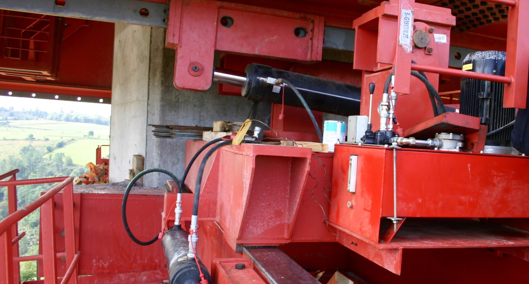
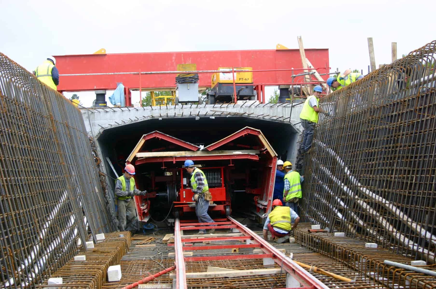
The methodological study aims to critically analyse how the adjustment and operation tasks of the Movable Scaffolding System are carried out. In each production cycle (preparation, lowering of the system, opening and closing of formwork, cambering adjustment, longitudinal launching, among other phases), different equipment subsystems are involved.Each of these phases can be broken down into elementary, observable, and repetitive operations that can be analysed and simplified.

It is precisely in this decomposition that the essence of MSS design lies: a functionally under-refined solution inevitably introduces supplementary work and unproductive time that could have been avoided at the design stage.
This decomposition allows the following questions to be raised:

  • Are the adjustment and operation subsystems of the Movable Scaffolding System the most appropriate?
  • Is the sequence of operations the most logical?
  • Are there tasks that could be eliminated?
  • Are there recurring manipulations or adjustments resulting from insufficiently refined design solutions?
  • Does the layout of working platforms and access ladders facilitate or hinder the work?
  • Is the number of levels that operators must access to adjust and operate the Movable Scaffolding System reduced to the minimum necessary?

The systematic application of these questions simplifies the operation and adjustment cycle of the MSS. However, it is important to emphasise that many of the operations carried out on site do not arise from unavoidable functional requirements, but rather from design choices related to the equipment’s own subsystems.

Whenever the MSS requires intermediate dismantling, recurring adjustments, complex reconfigurations, or auxiliary interventions to enable subsequent tasks, it generates additional work. This work does not add value to the span; it results from a design that has not been sufficiently optimised.
At this point, the technical responsibility of the MSS supplier becomes evident. Industrialisation depends not only on site organisation, but also on the functional quality of the system as designed. A well-engineered system should minimise handling operations, simplify interfaces, and reduce the number of operations required to adjust the equipment for each new span.

Time Study
Time study complements the method study by quantifying the actual duration of operations. The systematic repetition of adjustment and operational cycles in the MSS creates particularly favourable conditions for reliable time measurement and for the establishment of stable performance benchmarks.

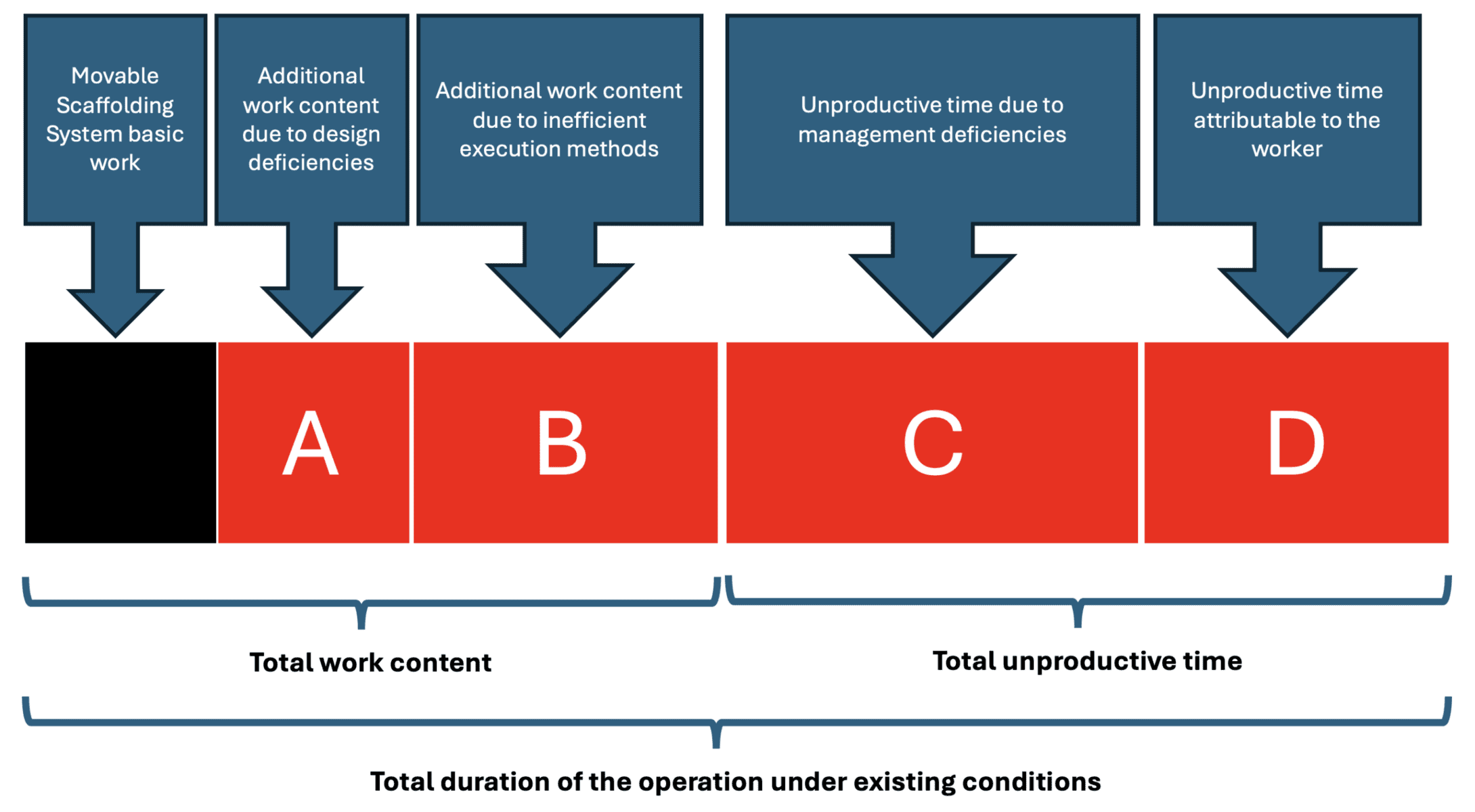
Time analysis makes it possible to clearly distinguish between:

  • Productive time (associated with fundamental work);
  • Supplementary time (resulting from avoidable operations);
  • Unproductive time (waiting, unnecessary movements, interferences).

By making these time components visible and measurable, an objective basis for continuous process improvement is established.
In systems characterised by repetitive use, such as the MSS, small inefficiencies accumulate over dozens of cycles and therefore significantly impact the overall cost of the project.
Every unnecessary movement, every avoidable adjustment, and every operational interference adds up to accumulated man-hours.

Responsibility in the Design of the MSS
A set of subsystems must be adjusted at each cycle to adapt the equipment for the next span. The way these subsystems are designed directly influences the amount of supplementary work generated.

The more complex the interfaces and the greater the number of interventions required to reconfigure the system, the greater the operational effort associated with the cycle. Systematic analysis of methods and times demonstrates that a substantial portion of supplementary work can be eliminated during the equipment design phase.

Structural and functional simplification of sub-systems reduces interventions, stabilises procedures, and decreases man-hours per span.
The application of work study principles to the MSS, therefore, leads to a clear conclusion: the system’s industrial maturity is measured by its capacity to reduce work to its fundamental form.

Responsibility for the industrialisation of deck construction does not lie solely with site organisation; it begins with the structural design of the bridge or viaduct and continues with the functional design of the MSS itself.

A supplier who designs solutions that require unnecessary operations effectively introduces additional work into the production system. Conversely, a functionally refined system enables the cycle to be executed with the fewest interventions, movements, and adjustments.

Industrialisation is not merely a management methodology; it is a direct consequence of the technical quality of the equipment design, enhanced by a well-conceived structural design of the concrete bridge or viaduct.

INTEGRATED SAFETY WITHIN THE SYSTEM
The consolidation of the MSS as a mature solution for the industrialisation of deck construction has required the development of a rigorous certification and technical compliance framework, particularly within the scope of the Machinery Directive.

By concentrating structural, operational, and safety functions within a single large-scale piece of equipment, the MSS ceases to be merely a formwork system and assumes the status of specialised construction equipment, subject to technical requirements comparable to those applicable to industrial machinery or complex temporary structures.
Its certification must encompass structural design verification, assessment of transient phases (assembly, concreting, launching, and dismantling), and the clear definition of operational limits.

The regulatory framework results from the combination of standards applicable to steel structures, work equipment, temporary structures, and collective protection systems, requiring an integrated approach from the design stage onward.

Technical responsibility is shared among the designer, the manufacturer, and the user. Comprehensive documentation is indispensable, including design criteria, calculation reports, assembly and operation drawings, dismantling procedures, reaction forces transmitted to the bridge or viaduct structure, operation manuals, checklists, manufacturing quality control documentation, risk assessments, parts lists with references and weights, and related technical records. MSS compliance depends not only on correct structural design but also on strict adherence to the defined operating conditions.

Prior to commissioning, the system must undergo appropriate tests and verifications. During operation, periodic inspections ensure continuous control of structural and functional performance. The very repetition of production cycles constitutes an ongoing opportunity to monitor and validate the equipment’s behaviour.

The standardisation of procedures (work methods, operational sequences, and acceptance criteria) reinforces the industrial logic of the MSS, reducing ad hoc decisions and promoting consistency, traceability, and operational discipline.

Certification should therefore not be regarded merely as a regulatory obligation, but as a structural component of risk management and system efficiency. It ensures that the industrialisation of deck construction using an MSS rests on sound technical foundations and is compatible with contemporary safety and quality requirements.

Far from being peripheral, certification and standardisation are integral components of the MSS concept, which is a factory in motion.

They guarantee that the industrialisation of prestressed concrete deck construction is supported by robust technical principles aligned with the demands of modern civil engineering in terms of safety, quality, and professional responsibility.

CONCLUSIONS

The Movable Scaffolding System represents one of the most advanced expressions of industrialization in the construction of prestressed reinforced concrete bridges and viaducts. Its true effectiveness, however, does not result solely from its structural capacity, but from its conception as an integrated production system.

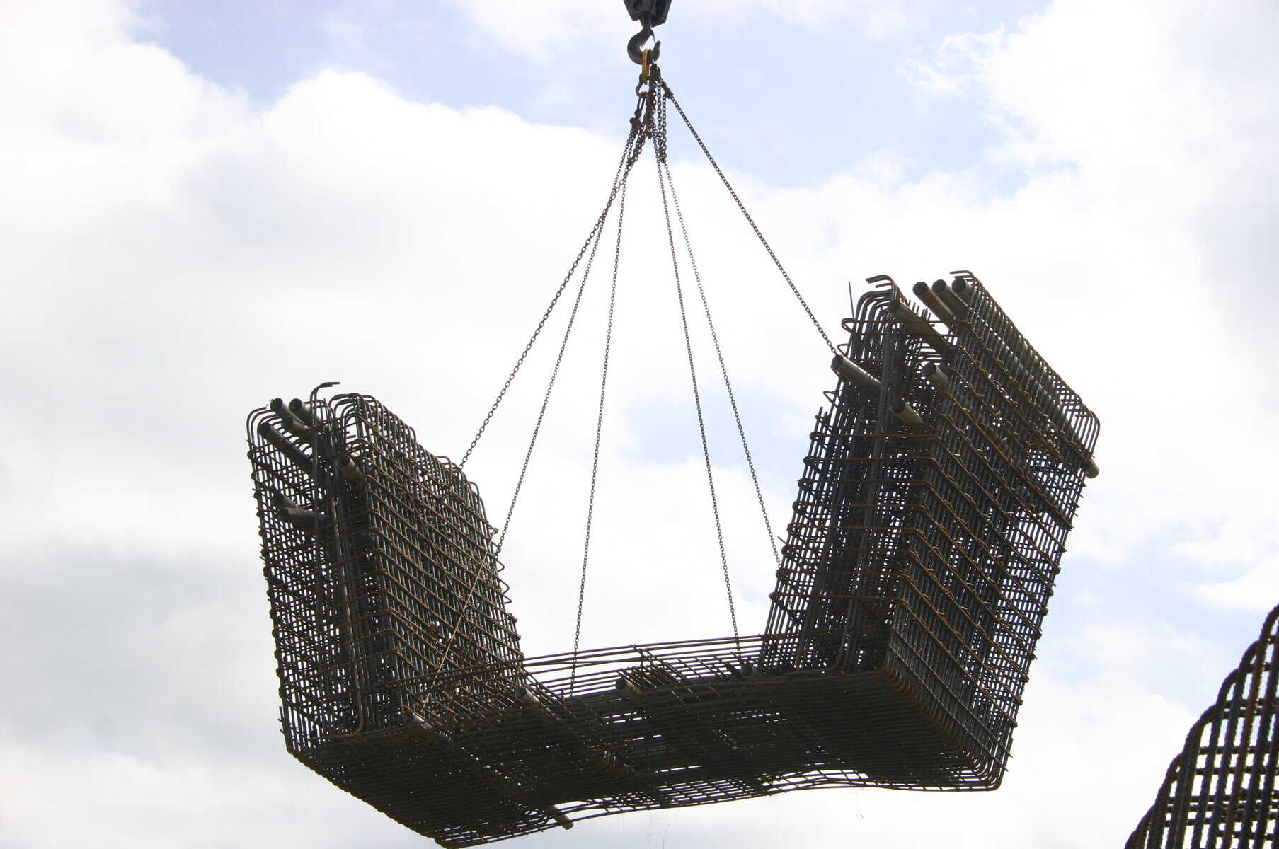
The industrialization of construction using a Movable Scaffolding System is based on three fundamental pillars: a structural bridge design oriented toward geometric simplicity and repetitiveness; rigorous organization of the production cycle as the primary unit of analysis; and the systematic application of work study methodologies aimed at eliminating supplementary work and unproductive time.

When these elements are properly aligned, the Movable Scaffolding System transforms the variability inherent to construction into a predictable, controlled, and progressively optimized process. The repetition of cycles enables the stabilization of methods, the reduction of crew size without compromising productivity, the enhancement of operational safety, and the strengthening of quality control. 

The industrial maturity of a Movable Scaffolding System is not measured solely by its structural design, but by its ability to simplify work, reduce ancillary interventions, and minimize unnecessary movements. The true refinement of the system lies in the continuous optimization of its subsystems and in the coherent integration between structural design, construction method, and work organization.

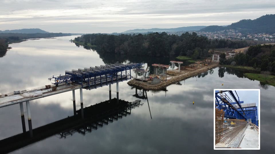
In this sense, the Movable Scaffolding System should not be understood merely as auxiliary construction equipment, but as a mobile industrial unit — a factory in motion — that carries its production environment with it, dissociating it from site constraints and bringing heavy construction closer to the organizational models of the manufacturing industry.

The industrialization of cast-in-place deck construction is therefore not an automatic consequence of using a Movable Scaffolding System; it is the result of a deliberate decision in terms of design, organization, and technical management. It is in this alignment that the true transformative potential of the system resides.

Author:
Aquilino Raimundo, Civil Engineer
Chief Methods Engineer, STRUKTURAS

Figure 10: General view of the underslung Movable Scaffolding System during launching

Excellent productivity using Overhead MSS at River Lima bridge construction in Portugal

Overhead MSS at River Lima bridge construction, Portugal

Overhead movable scaffolding system (OHMSS)
Highlights and facts:

  • Max Span: 33,0m
  • Min Span: 22,45m
  • Max MSS Span: 33,0m
  • Weight of Superstructure: Approx 26.2t/m
  • Width Of Bridge Slab: 15,9m
  • Max Crossfall: N.A.
  • Max Long Slope: 4,8%
Overhead MSS at River Lima bridge construction, Portugal

August 2025 Grupo ACA Construction team casted first span of 816m length river Lima bridge.

The Overhead movable scaffolding system of Strukturas created a perfect opportunity to reach maximum productivity – complete 25 spans in just 8 months.

Bridge construction is planning to by finished in March of 2026 as last spans and Overhead MSS will be demobilized.

This project is a true example of planning, coordination, and execution in large-scale infrastructure.

STRUKTURAS
WE MAKE IT SIMPLE! 

Post-tensioned concrete bridges

Norway Randselva bridge

POST-TENSIONED CONCRETE BRIDGES: DESIGN AND CONSTRUCTION USING THE SPAN-BY-SPAN METHOD WITH MOVABLE SCAFFOLDING SYSTEMS (MSS) AND BRIDGE INFORMATION MODELLING (BIM)

1. Introduction

The development of the MSS (Movable Scaffolding Systems) for long bridges using span by span methods has been intensively used in recent decades in Europe for a typical and optimal span range of 45m to 65m. The need and possibility of flexible horizontal and vertical track or road geometry together with optimal usage of post-tensioning on bridge decks has contributed significantly to the adoption of this design method in large scale road and railway projects currently in Poland.

The high-speed railway (HSR) design requirements meet very well this span-by-span bridge building method. Given the demanding parameters of HSR tracks, usually very long bridges at moderate heights are needed. These conditions are very suitable to MSS systems since this equipment is a launching span-by-span method that doesn’t introduce large launching forces at construction yard or on the piers. The versatility MSS building method allows its application on decks with variable horizontal curvature, with minimum radius of 250 m to 300 m.

This paper summarizes some bridge examples built by MSS method focusing on the different type of systems – underslung and overhead – and their main advantages, the various improvements on the concrete bridge decks cross sections and on the post-tensioning solutions typically considered. Optimizations on design and construction using a close interaction between designers, contractors and post-tensioning alternatives and/or suppliers will also be addressed.

Additionally, some examples and advantages of 3D model-based design solely developed using BIM models and with no drawings at the site will be presented. The main focus will be pointed to reinforcement/rebar optimizations and preassembling, as well as posttensioning layouts and improvements.

2. Rail requirements, local conditions and span arrangement

The design of bridges for high-speed trains is primarily governed by the substantial dynamic loads associated with train mass and velocity, which far exceed those considered in road structures, as well as by the large superimposed dead loads of the railway infrastructure.

The railway track consists of ballast, sleepers, rails and other equipment, which also represent significant additional loads, approximately three to four times greater than the remaining permanent load of road structures.

Superimposed dead loads (railway bridge on the left, road bridge on the right)

In general terms, it can also be said that the vertical overload due to rail traffic has values in the order of 100 kN/m per track, which, for the typical case of a two-track deck with a width of 14 m, results in a uniformly distributed load of 14.3 kN/m2, substantially higher than the traditional 4 kN/m2 considered for the overload of road structures.

Therefore, although for bridges intended for high-speed trains, the solutions generally correspond to those usually recommended on bridges and road viaducts, they must be adapted to the particular aspects that large loads and railway tracks impose.

The nature and size of the railway loads and decks stiffness requirements, justify the lower slenderness of this type of bridge structures when compared to the current values of road structures. In straight railway structures, the slenderness ratio between the height and the span of the deck, in continuous structures, is between 1/13 and 1/15, instead of the value of 1/20, considered as a reference in road structures.

Deck box-girder (ARITO SA) – typical cross section (HSR Porto-Lisbon track, Portugal 2025)

The width of the deck supporting the railway platform depends, of course, on the number of tracks, varying in the most common case – double track – between 12.5 m and 14.0 m. Whenever possible, however, there will be every interest in standardizing the width to allow a better optimization of the building method, the equipment effectiveness, the definition and maintenance of the track, etc.

In general, in railway viaducts with high ground hills that do not have special associated local constraints, the current trend is to use prestressed reinforced concrete structures with typical spans ranging from 45 m to 65 m, for which there is a broad consensus that the most suitable solution for the deck is the single-stage box girder cross-section, since with this typology an excellent use of the material is achieved, also ensuring adequate behavior for stiffness and for resistance to bending and torsion.

For this range of spans and cross-section typology, the choice of construction systems largely depends on the bridge length, height, and local geotechnical conditions. In general, the most commonly adopted method for deck construction involves self-launching Movable Scaffolding Systems (MSS), particularly when the bridge height is moderate to high (20 m < h < 70 m). Alternatively, ground-supported falsework is preferred when the bridge is relatively short (<150 m), the height is low (<25 m), and favorable foundation or support conditions are present. Furthermore, when opting for MSS, a minimum of four to five spans is typically considered good practice to ensure efficiency and cost-effectiveness. 

3. Underslung and overhead MSS

3.1. Underslung MSS

The Underslung MSS solution is currently employed in the construction of road and railway bridge decks, typically for spans ranging from 20 m to 70 m.

Concreting each box girder span using the Underslung MSS can be done in one or multiple stages, depending on the deck design. A single-stage casting is generally more cost-effective, as it enables faster construction cycles and reduces the quantity of post-tensioning required. Based on recent projects experience, it has been observed that two stages casting for box girders – dividing the deck into the U-shaped section and the upper slab – can increase post-tensioning quantities by approximately 20 to 30%.

In single-stage casting, the entire U-shaped deck cross-section including the slab (bottom slab, webs, and top slab) is cast in one operation using MSS. Main advantages are:

  • Faster cycle time (1 span per 7–10 days).
  • Monolithic structure with fewer joints, with increased durability.
  • Simplified post-tensioning since less tendons are used when compared to two-stage.

In two-stage casting, the deck is divided into two pours: Stage 1: Bottom slab and webs; Stage 2: Top slab (deck surface). As main advantages one can point out easier access for installing top slab reinforcement and ducts and better control of concrete quality and curing. However, other challenges arise such as longer construction time, and more careful joint treatment between stages.

Strukturas Underslung MSS
Vizela viaduct, Portugal (ARITO SA). Underslung MSS view from South. Typical spans of 56m

When two-stage casting is chosen external cables may be used for post-tension which makes less post tension cables inside the cross section itself but results in more complicated internal geometry for formwork system.

The versatility of the Underslung MSS solution allows its application on decks with variable horizontal curvature, with minimum radius of 250 m to 300 m.

The pursuit of simple yet effective construction solutions has been carried out for many years. Contactors, designers and MSS suppliers have collaborated intensively to optimize construction cycles, notably through the increased use of preassembled reinforcement wherever feasible.

3.2. Overhead MSS

Overhead MSS is another movable scaffolding system solution also suitable for casting boxgirder deck sections.

Both MSS configurations – Underslung or Overhead – share similar principles and functionalities. However, each system may offer distinct advantages depending on specific site conditions. For instance, the choice between them often depends on available vertical clearance and overall bridge height. If sufficient height is not available to accommodate an Underslung MSS, or if vertical clearance requirements cannot be met, the Overhead MSS may present a more viable alternative.

Vila Pouca de Aguiar viaduct, Portugal (ARITO SA). Casting and launching positions.

4. Other MSS and deck details

Several modern MSS systems also incorporate inner formworks equipped with rails and/or hydraulic mechanisms which, when paired with an appropriate deck design, can significantly enhance the efficiency of formworks relocation from span to span. As illustrated in Picture 6, the image on the left shows one of the systems used on Vila Pouca de Aguiar Viaduct in Portugal, where rail-based movement was utilized. On the right-hand side, the typical reinforcement assembly is shown, along with the arrangement of parabolic continuity tendons and bottom tendons as observed on site.

Modern inner formworks
Typical reinforcement assembly and parabolic tendons

As a result, by adopting a well-studied, organized and repetitive deck geometry, combined with strategic placement of post-tensioning blisters, a very straightforward and “clean” appearance is achieved within the deck interior, as illustrated in the pictures below.

Top blisters for upper (continuity) post-tensioning
Bottom blisters for lower post-tensioning

5. Model-based 3D design (BIM)

Drawings have played a central role in the construction industry for thousands of years serving as the primary medium for conveying information between design, planning, and execution phases. Until recently, they were considered the most important official channel for communication across disciplines.

Today, when referring to BIM (Building Information Modeling), most people think of digital 3D models. However, the term BIM also encompasses the broader workflow that facilitates seamless information exchange throughout the lifecycle of a structure—from planning and design to construction and maintenance.

Today, when referring to BIM (Building Information Modeling), most people think of digital 3D models. However, the term BIM also encompasses the broader workflow that facilitates seamless information-flow throughout the lifecycle of a structure – from planning and design to construction and maintenance.

Randselva bridge, Norway (ARITO SA), BIM model.

A drawing-less project, or the so-called model-based project, has the following advantages:

  • Understanding scope of work: A 3D-model greatly enhances the understanding of the scope of work during both planning and building. While a drawing gives a limited amount of information, like levels and measurements, a BIM-model gives the user the ability to access any information needed. Compared to a 2D-drawing, a BIM-model also gives the ability to sequence information.
  • Clash control: Finding, anticipating, and solving clashes in a BIM-model is much easier than on a 2D-drawing and cheaper than solving clashes on site.
  • Parametric design: BIM-models can be made with the help of parametric design. This way of working gives a lot of flexibility for design changes and saves a lot of time when working on repetitive tasks.
  • Cross border cooperation: A BIM-model looks the same in any country, while drawings usually are very country-specific. Thus, cross-country collaboration becomes easier.
  • Procurement: As all objects that need to be built or bought are represented in the model, accurate and updated data for volumes and quantities are always present in the BIM-model. Also, reinforcement can be ordered directly from the BIM-model, eliminating the need for manually made bar bending schedules.
  • Preparing for the future: If we want to improve automation in the construction industry, it’s essential to find alternatives to 2D-drawings when transferring information from design to site. Feeding 2D-drawings to robots or machines will not be optimal.

Choosing an optimal level of detail in a BIM-model is very important. Objects need to be modelled with enough details to be useful in clash control and understanding scope of work. At the same time, too many details will make model very large and software will start lagging and be difficult to control.

Post tensioning tendons and anchorages are important components in a bridge as they are the “arteries” of the bridge. The post tensioning geometry may be complex if it’s not wellthought, and the position of its components is not flexible. However, only the outer shape of the tendons geometry and anchorages is important to model correctly, as it will form the basis for clash control.

The steel strands and the inner geometry of the anchorages are handled by the supplier responsible for delivering the product and, in general, do not need to be modelled. Picture 9 illustrates a post tensioning drawing detail (top) and the equivalent area in a BIMmodel shown in perspective (bottom). They both carry information about post tensioning at the top and at the bottom of the cross-girder and how it will end in blisters where the anchorages are placed, either for continuity tendons or strengthening tendons, on the lower flange of the deck. The 3d-view does however offer a lot more information on potential clashes and a greatly improved understanding of scope of work even before one starts rotating the view. 

Comparison of traditional drawing design and model-based BIM design.

Another advantage of modelling all rebars is that reinforcement can be ordered directly from the BIM-model, removing the need for manually prepared bar bending schedules.

5. Conclusions

The span-by-span construction method using Movable Scaffolding Systems (MSS) has demonstrated its efficiency and adaptability in long-span bridge projects, particularly in highspeed railway (HSR) applications. The compatibility of MSS with demanding track geometry, heavy loads, and moderate heights makes it a preferred solution in large-scale infrastructure works. The choice between Underslung and Overhead systems depends on site-specific constraints, but both offer advantages in terms of construction speed, structural performance, and post-tensioning optimization.

The integration of model-based design through BIM has further enhanced the efficiency of MSS-based construction. By combining the repetitive and optimized geometry typical of MSS methods with the precision and clarity of BIM models, teams can preassemble reinforcement, streamline post-tensioning layouts, and reduce errors on site. The ability to visualize and coordinate all elements in 3D before execution supports faster cycles, cleaner deck interiors, and better collaboration between designers, contractors, and suppliers. This synergy between digital design and mechanized construction sets a strong foundation for future advancements in bridge engineering.

References

  1. Le viaduct de Vila Pouca au Portugal. Travaux. 2008, nr 853.
  2. ENGENHARIA SA, ARMANDO RITO, NORGE AS, SWECO. Detailed design of Randselva bridge, E16 Eggemoen – Åsbygda, 2019.
  3. Trimble’s World’s best BIM project and best BIM infrastructure project. https://www.tekla.com/bim-awards/randselva-bridge.
  4. VIEIRA T., ULVESTAD Ø., CABRAL P., GEICKE A. Randselva bridge, Norway – designing and building solely based on BIM models. W: fib Symposium 2021, Lisbon, 2021.

Article by Tiago VIEIRA

Strukturas attended 20th Wrocław Bridge Days

Strukturas was attending 20th Wrocław Bridge Days
Strukturas attended 20th Wrocław Bridge Days – Wrocław University of Science and Technology, 27-28 November 2025.
 

Linas Adomavičius and Maciej Masłowski met with numerous bridge professionals to discuss efficient and sustainable cast-in-situ bridge construction methods, including:

  • Span by span Movable Scaffolding System – MSS
  • Balanced Cantilever Form Travellers – FT

Tiago Vieira from ARMANDO RITO ENGENHARIA, SA made a very informative presentation about Movable Scaffolding System bridge design and best practices implemented together with Strukturas.


Poland is a very good example of Strukturas as cooperation with Hünnebeck by BrandSafway. Maciej Masłowski and Daniel Hutnik make this partnership strong.
 

Elbebrücke bridge construction using Underslung MSS

Elbebrücke bridge construction using Underslung MSS

Underslung MSS finishes the job at Elbebrücke construction site by ‪@ImpleniaTube‬ Consortium Implenia / DSD / Stahlbau Niesky has been awarded the contract for the construction of the new 1.1 km long Elbe bridge near Wittenberge. This project is the perfect example of sustainable and extreme bridge construction at sensitive and flood risk #NATURA2000 area. 

 Environmental aspects and sustainability play an important role in the planning and construction of the new bridge. The water levels of the Elbe have to be taken into account during construction.

Henning Schrewe, Head of Civil Engineering Germany at Implenia, commented: “We are delighted to be able to demonstrate our expertise in the planning and execution of challenging bridge projects with this contract. Winning this important contract also testifies to the consistent implementation of Implenia’s strategy of positioning itself as a partner for the realisation of complex major projects.”

Stukturas delivered underslung Movable Scaffolding System – MSS and site services related to MSS.

This MSS was special – a tower crane was placed on it. During launching the tower crane moves together with MSS. This cast in situ bridge construction equipment ensures high productivity and sustainability of Elbe bridge construction even when water level increases during river floods.

In 24 month MSS was used to build 2 parallel decks with 14 span each. This period includes the MSS relocation from 1st deck to 2nd.

STRUKTURAS
WE MAKE IT SIMPLE! 

Photo credits to Implenia.

We also leave here the podcast about this project for your further information:

https://impact.implenia.com/artikel/projekt-im-fokus-neubau-der-elbebruecke-bei-wittenberge/

5 pairs of Balanced Cantilever Form Travellers at the Morawica and Wola Morawicka bypasses

5 pairs of Balanced Cantilever Form Travellers at Construction of the Morawica and Wola Morawicka bypasses

5 pairs of Balanced Cantilever Form Travellers at the construction of the Morawica and Wola Morawicka bypasses in Poland.

The construction of the Morawica and Wola Morawicka bypass along National Road No. 73, class GP, from km 3+850.0 to 8+230.0 (section length: 4.38 km) is being carried out using the “Design and Build” system by Fabe Polska Sp. z o.o. The scope of construction includes the construction of two road structures with the following parameters.

ED-2 viaduct over the Czarna Nida River:

  • Continuous, five-span structure
  • Span length: 75.15 + 2 x 108.00 + 98.0 + 65.15
  • Total length of the structure: 456.30 m
  • Total width of the structure: 11.40 + 1.70 + 11.40 m

ED-5 overpass over the river Morawka:

  • Continuous, four-span structure
  • Span length: 63.50 + 99.00 + 99.00 + 63.50 m
  • Total length of the structure: 327.00 m
  • Total width of the structure: 11.40 + 1.70 + 11.40 m

Highlighs & Facts of Strukturas Form Travellers:

  • Max. Segments length: 5,0 m
  • Max. width superstructure = 11,78 m
  • Length of hammerhead: 13,0 m
  • Min. hor. radius: STRAIGHT
  • Max. longitudinal slope: 0,7 %
  • Section cross fall: 2,5 %
  • Weight of heaviest segment: 154 TONS
  • Highest Segment height: 4,92 m
  • Lowest Segment height: 2,5 m
  • Min. Distance to neighbor bridge: 2,07 m
  • The maximum allowable deflection of the Main Girder due to concrete load is approx.: L/400
  • The maximum allowable deflection for other structural members: L/250

STRUKTURAS
WE MAKE IT SIMPLE!

Video Credits to Fabe Polska Sp. z o.o..

Stay tuned for this project and follow us on social media to updates.

Anna Jagiellon Bridge construction in Poland (Warsaw) using 3 different systems

Anna Jagiellon Bridge, Warsaw, Poland construction using Form Travellers, Overheard Movable Scaffolding System and Wing Form Travellers
The project:
 
The new Vistula crossing integrated into the S2 Expressway and consists of two parallel decks with the following lengths:
•   Central bridge MG04-02 measuring 536.5 m per deck;
•   MG04-01 and MG04-03 access viaducts with a total of 970 m per deck.
 
The client:

GP Mosty JV Gülermak Heavy Industries Construction & Contracting Co. Inc Branch in Poland and PBDiM Mińsk Mazowiecki

The Balanced Cantilever FT solution:
The main characteristic of the Vistula cantilever bridge deck crossing the river, is the fact that it has pre casted concrete struts to support the outer wings, as well as another precast strut installed inside the deck box in between the webs.The prefabricated struts normally difficult the Form traveller operation, as they interfere with the webs and top slab formwork. 
 
In the Vistula case the solution allows to operate the Form travellers basically in a standard way, since the webs formwork panels incorporate some slots aligned with both ends of the precast concrete struts. These slots are closed during the concerting stage, being opened before the formwork is prepared for the Form traveller launching.

The installation of the external precast struts is made as soon as the Form traveller is adjusted to its position at the new segment. The external deck wings top slab formwork panels are equipped with an opening through which the pre cast struts will pass. This opening will be closed by a plywood plate before the rebar works start. The pre cast struts will stay on top of adjustable supports delivered with the Form traveller formwork system.

The internal pre cast strut will be placed in a awaiting position on top of the bottom slab rebar, inside the deck box before the Form traveller internal formwork is launched forward. After the internal formwork is launched to its final position and adjusted, then the internal precast strut will be lifted, rotated and installed at its final position in between the deck webs.

The OHMSS and WFT solution:
 
Taking into account conditions and location of construction site, Overhead Movable Scaffolding System (OHMSS) combined with a Wing Formtraveller (WFT) solutions were implemented.
 

The OHMSS was used for concreting the central deck box and the WFT used to install the pre­ cast struts and concrete the wings.

The broad range of technical requirements used during the design phase of the OHMSS included the following features: 

  • the outer formwork of the OHMSS must be possible to open when free distance to the ground is only 3.0m;
  • the outer formwork must be able to pass in the closed position over the existing railway without reaching a height of more than 0.7 m;
  • the rebar U-cages (bottom slab and webs) of the deck must allow for assembly in 12 m sections and in the final position using the transport devices that equip the OHMSS;
  • the sections of the rebar U-cages of the deck must allow for lifting from ground level or as an alternative be transported over the deck that has already been built and later moved through the inside of the OHMSS main structure through its rear support;
  • the deck shall be concreted in two phases, the first phase involving the concreting of the central box using the OHMSS, the second phase involving the installation of the pre-fabricated struts of the deck wings and the concreting of the wings itself using the WFT;
  • allow for the OHMSS to move backward to the abutment and proceed with a side-shift to the alignment of the second deck parallel to the first one;
  • allow for the passing of the OHMSS through the WFT, after dismantling the OHMSS external formwork and without needing to dismantle the WFT (only its 4 legs are dismantled);
  • allow for the forward movement of the OHMSS passing over the deck of the central bridge to the opposite shore of the Vistula River.

Stay tuned for more projects like this and follow us on social media for updates.

STRUKTURAS
WE MAKE IT SIMPLE!

Movable scaffolding system (MSS) mobilisation at Rail Baltica Neris bridge

MSS rail baltica Neris bridge

We are thrilled to announce that Strukturas started mobilisation of the Underslung Movable Scaffolding System MSS tailored to the unique High Speed Railway bridge over Neris river in Lithuania.

The project owner LTG Infra awarded construction of this bridge to Italian contractor Rizzani de Eccher

1,5 km-long bridge – the longest bridge ever built not only in Lithuania but in the Baltics.

The project will be implemented in strict compliance with the regulations for the protection of the nearby Natura 2000 site.

What is special about Strukturas MSS technical solution?

  • MSS construction method ensures minimal interference with nature, traffic and private property.
  • MSS Mezio will be utilised for NERIS bridge, it what was produced 2005 for viaduct MEZIO, Portugal and running on sharing economy base over 20 years in multiple bridges in Europe. This shows Strukturas sustainable approach for designing and utilising machines with long lifespan creating minimal CO2 emission footprint.
  • MSS will be used with tower crane on top. Tower crane will be launched with MSS.
  • Fresh concrete loads will be transferred not to the pier, but to the pier foundation.
  • Tailored Hydraulic Internal formwork will be used to boost construction productivity.
  • Typical cycle is expected 2 week/span.

MSS Neris Key facts:

  • Max span: 45,0m 
  • Max. MSS span: 36,35m
  • Weight of superstructure: 28,8t/m 
  • Width of superstructure: 13,9m
  • Min hor. radius: R = 3965m
  • Max long. Slope: 0,25%
  • Bridge length: 1510,0m 

Stay tuned for this project and follow us on social media to updates.

Balanced cantilever bridge project – Rader Hochbrücke / BAB A7

Balanced cantilever bridge project - Rader Hochbrücke / BAB A7

We are thrilled to announce that Strukturas started mobilisation of the Special Balanced Cantilever Formwork tailored to the unique engineering challenge of Implenia.

The new Rader bridge Key facts:

✔️1,500m long and 42m high.

✔️Concrete in situ: 49,815 m³

✔️Reinforcement Civil: 9,079 t

✔️Precast Concrete: 1,890 m³

DOWNLOAD 9 Pages ARTICLE ABOUT THIS PROJECT IN GERMAN LANGUAGE

What is special about Strukturas solution?

  • Tailored for Concreting the massive and geometrically narrow complex hammerhead to extend additional long and heavy segments using the balanced cantilever method.
  • Prepared for the installation by incremental launching of a steel deck that will seamlessly overlay the partially concreted hammerhead.
  • Allows continued concreting the hammerhead under the steel deck, integrating it with the deck while maintaining full support and precision.
  • This innovative solution minimise crane and labour needs through hydraulic adjustments, while keeping the Special Form Traveller in place to ensure precise geometry and alignment.

Stay tuned for this project and follow us on social media to updates.

Strukturas GmbH at VDI Wissensforum GmbH Konferenz Rückbau von Brücken

VDI Wissensforum GmbH Konferenz Rückbau von Brücken
Strukturas GmbH has participated at bridge demolition conference 2025.
 
The venue had a hall for participants to have a great networking space.
 
Therefore Strukturas GmbH managing director Stefan Flachhuber and Strukturas AS managing director Øyvind Karlsen took a possibility to have a booth at conference hall to meet the visitors. They are happy for all the contacts and interesting conversations.
 
With their extensive expertise in bridge construction they are are leading our activities in Germany, Austria and Switzerland.
If you missed this event and want to discus bridge building equipment solutions in Germany, Austria or Switzerland please contact:
 
STRUKTURAS GmbH
Wallbrunnstrasse 24
D-79539 LÖRRACH
Tel.: +49 155 6007 8114