
POST-TENSIONED CONCRETE BRIDGES: DESIGN AND CONSTRUCTION USING THE SPAN-BY-SPAN METHOD WITH MOVABLE SCAFFOLDING SYSTEMS (MSS) AND BRIDGE INFORMATION MODELLING (BIM)
1. Introduction
The development of the MSS (Movable Scaffolding Systems) for long bridges using span by span methods has been intensively used in recent decades in Europe for a typical and optimal span range of 45m to 65m. The need and possibility of flexible horizontal and vertical track or road geometry together with optimal usage of post-tensioning on bridge decks has contributed significantly to the adoption of this design method in large scale road and railway projects currently in Poland.
The high-speed railway (HSR) design requirements meet very well this span-by-span bridge building method. Given the demanding parameters of HSR tracks, usually very long bridges at moderate heights are needed. These conditions are very suitable to MSS systems since this equipment is a launching span-by-span method that doesn’t introduce large launching forces at construction yard or on the piers. The versatility MSS building method allows its application on decks with variable horizontal curvature, with minimum radius of 250 m to 300 m.
This paper summarizes some bridge examples built by MSS method focusing on the different type of systems – underslung and overhead – and their main advantages, the various improvements on the concrete bridge decks cross sections and on the post-tensioning solutions typically considered. Optimizations on design and construction using a close interaction between designers, contractors and post-tensioning alternatives and/or suppliers will also be addressed.
Additionally, some examples and advantages of 3D model-based design solely developed using BIM models and with no drawings at the site will be presented. The main focus will be pointed to reinforcement/rebar optimizations and preassembling, as well as posttensioning layouts and improvements.
2. Rail requirements, local conditions and span arrangement
The design of bridges for high-speed trains is primarily governed by the substantial dynamic loads associated with train mass and velocity, which far exceed those considered in road structures, as well as by the large superimposed dead loads of the railway infrastructure.
The railway track consists of ballast, sleepers, rails and other equipment, which also represent significant additional loads, approximately three to four times greater than the remaining permanent load of road structures.

In general terms, it can also be said that the vertical overload due to rail traffic has values in the order of 100 kN/m per track, which, for the typical case of a two-track deck with a width of 14 m, results in a uniformly distributed load of 14.3 kN/m2, substantially higher than the traditional 4 kN/m2 considered for the overload of road structures.
Therefore, although for bridges intended for high-speed trains, the solutions generally correspond to those usually recommended on bridges and road viaducts, they must be adapted to the particular aspects that large loads and railway tracks impose.
The nature and size of the railway loads and decks stiffness requirements, justify the lower slenderness of this type of bridge structures when compared to the current values of road structures. In straight railway structures, the slenderness ratio between the height and the span of the deck, in continuous structures, is between 1/13 and 1/15, instead of the value of 1/20, considered as a reference in road structures.

The width of the deck supporting the railway platform depends, of course, on the number of tracks, varying in the most common case – double track – between 12.5 m and 14.0 m. Whenever possible, however, there will be every interest in standardizing the width to allow a better optimization of the building method, the equipment effectiveness, the definition and maintenance of the track, etc.
In general, in railway viaducts with high ground hills that do not have special associated local constraints, the current trend is to use prestressed reinforced concrete structures with typical spans ranging from 45 m to 65 m, for which there is a broad consensus that the most suitable solution for the deck is the single-stage box girder cross-section, since with this typology an excellent use of the material is achieved, also ensuring adequate behavior for stiffness and for resistance to bending and torsion.
For this range of spans and cross-section typology, the choice of construction systems largely depends on the bridge length, height, and local geotechnical conditions. In general, the most commonly adopted method for deck construction involves self-launching Movable Scaffolding Systems (MSS), particularly when the bridge height is moderate to high (20 m < h < 70 m). Alternatively, ground-supported falsework is preferred when the bridge is relatively short (<150 m), the height is low (<25 m), and favorable foundation or support conditions are present. Furthermore, when opting for MSS, a minimum of four to five spans is typically considered good practice to ensure efficiency and cost-effectiveness.
3. Underslung and overhead MSS
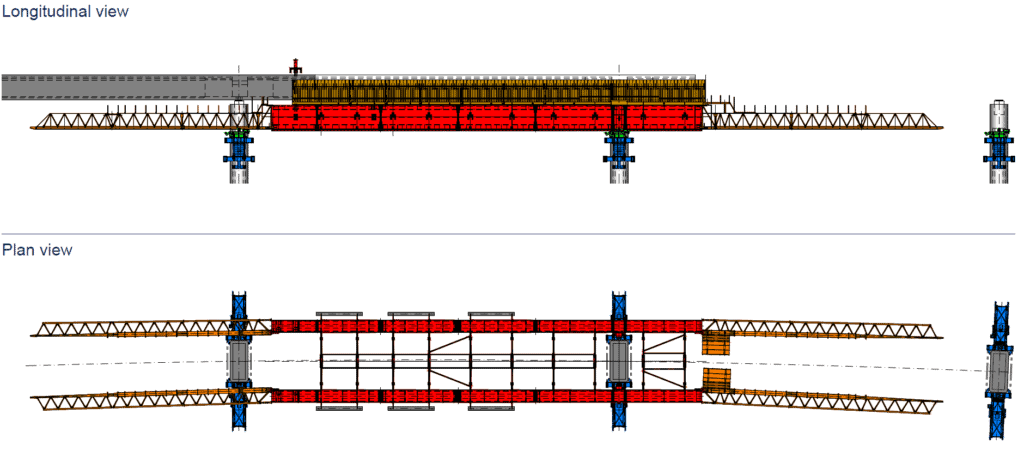
3.1. Underslung MSS
The Underslung MSS solution is currently employed in the construction of road and railway bridge decks, typically for spans ranging from 20 m to 70 m.
Concreting each box girder span using the Underslung MSS can be done in one or multiple stages, depending on the deck design. A single-stage casting is generally more cost-effective, as it enables faster construction cycles and reduces the quantity of post-tensioning required. Based on recent projects experience, it has been observed that two stages casting for box girders – dividing the deck into the U-shaped section and the upper slab – can increase post-tensioning quantities by approximately 20 to 30%.
In single-stage casting, the entire U-shaped deck cross-section including the slab (bottom slab, webs, and top slab) is cast in one operation using MSS. Main advantages are:
- Faster cycle time (1 span per 7–10 days).
- Monolithic structure with fewer joints, with increased durability.
- Simplified post-tensioning since less tendons are used when compared to two-stage.
In two-stage casting, the deck is divided into two pours: Stage 1: Bottom slab and webs; Stage 2: Top slab (deck surface). As main advantages one can point out easier access for installing top slab reinforcement and ducts and better control of concrete quality and curing. However, other challenges arise such as longer construction time, and more careful joint treatment between stages.

When two-stage casting is chosen external cables may be used for post-tension which makes less post tension cables inside the cross section itself but results in more complicated internal geometry for formwork system.
The versatility of the Underslung MSS solution allows its application on decks with variable horizontal curvature, with minimum radius of 250 m to 300 m.
The pursuit of simple yet effective construction solutions has been carried out for many years. Contactors, designers and MSS suppliers have collaborated intensively to optimize construction cycles, notably through the increased use of preassembled reinforcement wherever feasible.
3.2. Overhead MSS
Overhead MSS is another movable scaffolding system solution also suitable for casting boxgirder deck sections.
Both MSS configurations – Underslung or Overhead – share similar principles and functionalities. However, each system may offer distinct advantages depending on specific site conditions. For instance, the choice between them often depends on available vertical clearance and overall bridge height. If sufficient height is not available to accommodate an Underslung MSS, or if vertical clearance requirements cannot be met, the Overhead MSS may present a more viable alternative.

4. Other MSS and deck details
Several modern MSS systems also incorporate inner formworks equipped with rails and/or hydraulic mechanisms which, when paired with an appropriate deck design, can significantly enhance the efficiency of formworks relocation from span to span. As illustrated in Picture 6, the image on the left shows one of the systems used on Vila Pouca de Aguiar Viaduct in Portugal, where rail-based movement was utilized. On the right-hand side, the typical reinforcement assembly is shown, along with the arrangement of parabolic continuity tendons and bottom tendons as observed on site.


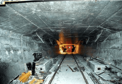
As a result, by adopting a well-studied, organized and repetitive deck geometry, combined with strategic placement of post-tensioning blisters, a very straightforward and “clean” appearance is achieved within the deck interior, as illustrated in the pictures below.

5. Model-based 3D design (BIM)
Drawings have played a central role in the construction industry for thousands of years serving as the primary medium for conveying information between design, planning, and execution phases. Until recently, they were considered the most important official channel for communication across disciplines.
Today, when referring to BIM (Building Information Modeling), most people think of digital 3D models. However, the term BIM also encompasses the broader workflow that facilitates seamless information exchange throughout the lifecycle of a structure—from planning and design to construction and maintenance.
Today, when referring to BIM (Building Information Modeling), most people think of digital 3D models. However, the term BIM also encompasses the broader workflow that facilitates seamless information-flow throughout the lifecycle of a structure – from planning and design to construction and maintenance.

A drawing-less project, or the so-called model-based project, has the following advantages:
- Understanding scope of work: A 3D-model greatly enhances the understanding of the scope of work during both planning and building. While a drawing gives a limited amount of information, like levels and measurements, a BIM-model gives the user the ability to access any information needed. Compared to a 2D-drawing, a BIM-model also gives the ability to sequence information.
- Clash control: Finding, anticipating, and solving clashes in a BIM-model is much easier than on a 2D-drawing and cheaper than solving clashes on site.
- Parametric design: BIM-models can be made with the help of parametric design. This way of working gives a lot of flexibility for design changes and saves a lot of time when working on repetitive tasks.
- Cross border cooperation: A BIM-model looks the same in any country, while drawings usually are very country-specific. Thus, cross-country collaboration becomes easier.
- Procurement: As all objects that need to be built or bought are represented in the model, accurate and updated data for volumes and quantities are always present in the BIM-model. Also, reinforcement can be ordered directly from the BIM-model, eliminating the need for manually made bar bending schedules.
- Preparing for the future: If we want to improve automation in the construction industry, it’s essential to find alternatives to 2D-drawings when transferring information from design to site. Feeding 2D-drawings to robots or machines will not be optimal.
Choosing an optimal level of detail in a BIM-model is very important. Objects need to be modelled with enough details to be useful in clash control and understanding scope of work. At the same time, too many details will make model very large and software will start lagging and be difficult to control.
Post tensioning tendons and anchorages are important components in a bridge as they are the “arteries” of the bridge. The post tensioning geometry may be complex if it’s not wellthought, and the position of its components is not flexible. However, only the outer shape of the tendons geometry and anchorages is important to model correctly, as it will form the basis for clash control.
The steel strands and the inner geometry of the anchorages are handled by the supplier responsible for delivering the product and, in general, do not need to be modelled. Picture 9 illustrates a post tensioning drawing detail (top) and the equivalent area in a BIMmodel shown in perspective (bottom). They both carry information about post tensioning at the top and at the bottom of the cross-girder and how it will end in blisters where the anchorages are placed, either for continuity tendons or strengthening tendons, on the lower flange of the deck. The 3d-view does however offer a lot more information on potential clashes and a greatly improved understanding of scope of work even before one starts rotating the view.

Another advantage of modelling all rebars is that reinforcement can be ordered directly from the BIM-model, removing the need for manually prepared bar bending schedules.
5. Conclusions
The span-by-span construction method using Movable Scaffolding Systems (MSS) has demonstrated its efficiency and adaptability in long-span bridge projects, particularly in highspeed railway (HSR) applications. The compatibility of MSS with demanding track geometry, heavy loads, and moderate heights makes it a preferred solution in large-scale infrastructure works. The choice between Underslung and Overhead systems depends on site-specific constraints, but both offer advantages in terms of construction speed, structural performance, and post-tensioning optimization.
The integration of model-based design through BIM has further enhanced the efficiency of MSS-based construction. By combining the repetitive and optimized geometry typical of MSS methods with the precision and clarity of BIM models, teams can preassemble reinforcement, streamline post-tensioning layouts, and reduce errors on site. The ability to visualize and coordinate all elements in 3D before execution supports faster cycles, cleaner deck interiors, and better collaboration between designers, contractors, and suppliers. This synergy between digital design and mechanized construction sets a strong foundation for future advancements in bridge engineering.
References
- Le viaduct de Vila Pouca au Portugal. Travaux. 2008, nr 853.
- ENGENHARIA SA, ARMANDO RITO, NORGE AS, SWECO. Detailed design of Randselva bridge, E16 Eggemoen – Åsbygda, 2019.
- Trimble’s World’s best BIM project and best BIM infrastructure project. https://www.tekla.com/bim-awards/randselva-bridge.
- VIEIRA T., ULVESTAD Ø., CABRAL P., GEICKE A. Randselva bridge, Norway – designing and building solely based on BIM models. W: fib Symposium 2021, Lisbon, 2021.
Article by Tiago VIEIRA